Guides / Buyer Guide
Aluminum Alloy Thermal Conductivity and What It Means for Motor Housing Cooling
Written by the team that reads your RFQPublished How we write these
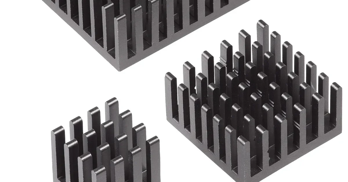
A motor turns part of its input power into heat, mostly in the windings and the stator core. That heat has to reach the outside air or a coolant, and in many motors the aluminum housing carries it the last stretch. Aluminum is chosen partly for this reason. Alloys do not all conduct equally, so a buyer asked to choose or approve an alloy may wonder how much the choice matters.
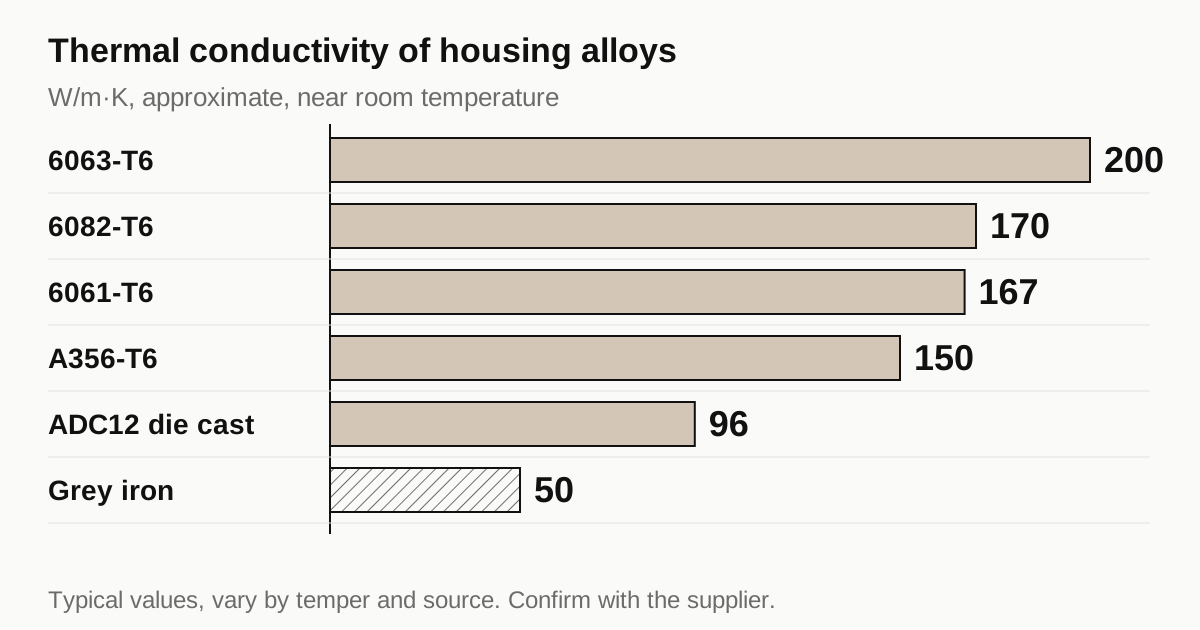
This guide lists typical conductivity values, shows with a simple calculation where the alloy matters and where it does not and describes what to write on a drawing.
Typical values by alloy
Thermal conductivity, written k, is the heat that flows through a unit of material for each degree of temperature difference. Higher is better for moving heat out.
| Material | Typical thermal conductivity near room temperature |
|---|---|
| Pure aluminum, 1050 | About 230 W/m.K |
| 6063-T6 extrusion | About 200 W/m.K |
| 6082-T6 | About 170 W/m.K |
| 6061-T6 | About 167 W/m.K |
| A356-T6 cast | About 150 W/m.K |
| ADC12 / A380 die cast | About 95 to 100 W/m.K |
| Grey cast iron | About 45 to 55 W/m.K |
| Carbon steel, 4140 | About 42 W/m.K |
These are typical values from published handbooks. Data differ between sources, tempers and temperature, and some alloy values in the literature are given as ranges. Ask a supplier for a certificate or a data sheet if a design depends on a figure.
The pattern is clear. Wrought aluminum conducts best, and cast alloys give up some conductivity because their silicon and copper contents scatter heat carriers. Die cast alloys sit near half the value of 6063. All aluminum alloys still beat iron and steel by a wide margin, which explains why aluminum housings run cooler for the same size.
Where the heat goes
The heat path from a winding to the outside runs through several layers in series.
- Winding to stator core, through insulation and slot liner.
- Stator core to housing bore, across the interface between laminations and the housing.
- Through the housing wall.
- From the outer surface to the coolant or air, through a thin boundary layer.
Each step adds thermal resistance, and the total temperature rise is the sum. The alloy’s conductivity affects only step 3.
A worked comparison
Thermal resistance of a flat wall per unit area is the wall thickness divided by the conductivity, R = t / k. For a 5 mm wall:
| Alloy | k | Wall resistance, m2.K/W |
|---|---|---|
| 6063-T6 | 200 | 0.000025 |
| 6061-T6 | 167 | 0.000030 |
| A356-T6 | 150 | 0.000033 |
| ADC12 | 96 | 0.000052 |
Now compare with the boundary layer on the outside. Resistance is 1 / h, where h is the heat transfer coefficient. Typical order of magnitude values are:
- Water or water glycol jacket: h from about 1,000 to 5,000 W/m2.K, so a resistance of about 0.0002 to 0.001 m2.K/W.
- Still or fan driven air over fins: h from about 10 to 50 W/m2.K, so a resistance of about 0.02 to 0.1 m2.K/W.
These h values are orders of magnitude for orientation. Real values depend on flow, geometry and fluid.
The result is a useful lesson. Even for a water jacket, the ADC12 wall resistance of 0.000052 is small next to a boundary layer of 0.0002 to 0.001. The alloy choice moves the wall resistance by a factor of two, but the wall is only a modest part of the total. For an air cooled finned housing, the wall resistance is almost negligible against the air film.
That is why changing from ADC12 to 6063 rarely changes a motor’s temperature much. The real gains lie in the other three steps.
A temperature drop example
Take a water jacketed housing that must remove heat at a flux of 20,000 W per square meter of jacket wall. That figure is an illustration, not a design value. The temperature drop across each layer is the flux multiplied by the resistance of the layer.
| Layer | Resistance, m2.K/W | Temperature drop at 20,000 W/m2 |
|---|---|---|
| Wall, 5 mm ADC12 | 0.000052 | About 1.0 K |
| Wall, 5 mm 6063-T6 | 0.000025 | About 0.5 K |
| Water boundary layer at h = 2,000 | 0.0005 | About 10 K |
| Interface gap, 0.02 mm of air | About 0.0008 | About 16 K |
The interface row uses air at about 0.025 W/m.K across 0.02 mm. The point is the size of the number, not its precision. A thin air gap between stator and housing can cost more temperature than the whole choice of alloy. Closing the gap with a proper shrink fit or a thermal paste can do more for motor temperature than any alloy change.
The example also shows why designers sometimes go the other way and accept a cheaper alloy. Switching from 6063 to ADC12 adds roughly half a kelvin in this case, and a die casting is far cheaper per part than a machined extrusion at volume. The designer weighs a small temperature penalty against a large cost saving.
Contact resistance at the bore
The interface between the laminated stator and the housing bore is the least predictable part of the path. Heat has to cross microscopic contact points between two rough surfaces, with air filling the gaps.
Things that improve contact:
- A true, round bore that matches the stator outer diameter along its full length.
- A controlled interference that presses the surfaces together.
- A moderate surface finish. Too rough leaves voids. A very smooth bore can slip, as the shrink fit guide describes.
- Thermal compounds or potting in designs that use a slip fit.
Things that hurt contact:
- A bore that is tapered or oval.
- Burrs and chips left on the bore before the stator goes in.
- A coating left on the bore by mistake.
For a buyer, this is a practical reason to treat bore roundness and cleanliness as thermal requirements as well as mechanical ones.
Need a quote for this part? Get a quote for your motor part
Cast alloys and wrought alloys
The choice between cast and wrought material is usually made by cost and shape, and conductivity follows.
Wrought and extruded alloys such as 6063 and 6061 conduct best. They suit simple shapes: tubes, finned profiles and machined billet.
Gravity and low pressure cast alloys such as A356 conduct a little less and suit mid volume jobs with complex shapes.
High pressure die cast alloys such as ADC12 and A380 conduct the least. They allow thin walls, fins and integrated features in one shot, at the lowest cost per part in volume.
The thermal penalty of a cast alloy can be offset by features that a casting makes possible, such as longer fin area or a jacket shape that would be impossible to machine. Judging an alloy by its conductivity alone ignores that.
Where conductivity numbers come from
Published values come from laser flash, steady state comparison or electrical conductivity tests, since electrical and thermal conductivity are related in metals. Different methods and different samples give different numbers, and tempers shift them. Two handbooks may list values that differ by ten percent for the same alloy.
If a design depends on a conductivity value, ask the material supplier for a measured value on the lot, with the method. Otherwise use the handbook value as an estimate and keep a margin. The housing and shaft machining guide explains how drawings normally state material.
What matters more than the alloy
The stator to housing interface. A shrink fit with a clean, round bore makes good thermal contact. A loose or oval fit leaves air gaps, and air is an insulator. The bore size and roundness set the contact. The guide to shrink fit and roundness explains how the machined bore affects this.
Surface area and fin design. On an air cooled motor, more fin area and better airflow reduce the boundary layer resistance, which is the dominant term.
Jacket geometry and coolant flow. A well designed jacket with turbulent flow and no dead zones cuts the boundary layer resistance. A jacket with dead corners wastes area.
Wall thickness. Halving the wall halves the wall resistance, which in some cases helps more than a change of alloy. Thin walls cost more to machine, as the thin-wall guide explains.
Coatings. A thick coat on a finned housing adds resistance at the surface. The coating guide compares typical thicknesses.
When the alloy does matter
Alloy choice is more important in a few cases.
- High power density motors, where each degree counts, such as traction motors.
- Thick sections, such as a large cast end shield or a thick mounting flange that carries heat a long way.
- Local hot spots, where heat has to spread across a plate before it reaches the coolant. Spreading depends on conductivity times thickness.
- Lightweight designs, where a thin wall in high conductivity alloy replaces a thick wall in a poorer one.
In these cases, a designer runs a thermal model and picks the alloy from it. A buyer should not change the alloy at the RFQ stage without the designer’s approval.
What to write on the drawing
- Alloy and temper, with the standard, not just “aluminum”.
- Any minimum thermal conductivity, only if the design really depends on it, with the test method.
- Bore size, roundness and surface finish at the stator interface.
- Wall thickness minimum after machining.
- Coating or finish on cooling surfaces.
Checklist before you send the RFQ
- State alloy and temper with a standard.
- Mark the surfaces that carry heat, such as the bore and the cooling surfaces.
- Give bore limits and roundness for the stator interface.
- State minimum wall thickness.
- Say whether the housing is cast, extruded or machined from bar, since the route sets the available alloys.
When the drawing is ready, send the RFQ and we quote the finished parts and place the work with a partner shop that machines motor housings. Replies come within 24 business hours.
Standards and references
- Thermal conductivity, overview with values for common materials. Reference ranges for aluminum, iron and steel. Alloy values vary by temper and source.
- Aluminium alloy, overview of wrought and cast families. Why casting alloys with more silicon conduct less than wrought alloys.
- Die casting, overview of the process and typical alloys. Background on the alloys used for cast housings.
- ASM Handbook, Volume 2: Properties and Selection of Nonferrous Alloys and Special-Purpose Materials. A standard reference for alloy thermal properties. Values differ between editions and tempers.
Figures on this page are typical ranges drawn from the standards above and from ordinary shop practice. They are not a specification for your part. The partner shop that prices your part confirms what it can hold on your geometry.
Frequently asked questions
Which aluminum alloy conducts heat best for a motor housing?
Among the common alloys, the 6000 series wrought alloys such as 6063 conduct best, with cast alloys such as A356 lower and die cast ADC12 or A380 lowest. The difference is real, but for most housings it is a small part of the total thermal path.
Should I switch alloy to run the motor cooler?
Only after checking where the temperature drop actually sits. In most motors the largest drops are at the interface between stator and housing and at the cooling surface, not in the housing wall. Changing alloy helps less than improving the stator fit or the coolant flow.
Do tempers and heat treatment change conductivity?
Yes. Heat treated tempers shift conductivity, usually lowering it compared with the annealed state because alloying elements in solution scatter heat carriers. The change is modest, and data sheets give values per temper.
Need a quote for this part?
Send the drawing. We quote the finished parts, place the work with a partner shop and reply within 24 business hours.
Get a quote for your motor part