Guides / Tolerances
Machining Thin-Wall Motor Housings Without Distortion
Written by the team that reads your RFQPublished How we write these
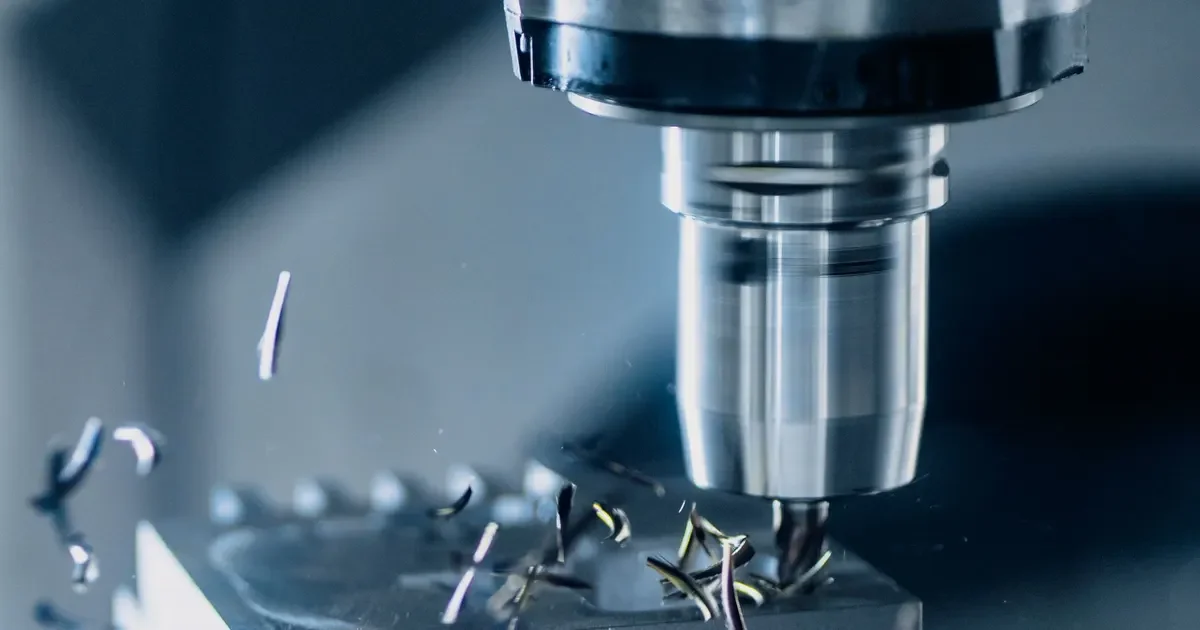
A motor housing with a thin wall can leave the machine with a perfect bore and arrive at the bearing seat with an oval one. Nothing was cut wrong. The wall moved when the clamp opened, or when the part cooled, or a few hours later when internal stress let go. That movement is the main reason thin-wall housings cost more than their material suggests.
This guide covers the four things that move a thin wall, the process steps shops use to control each one and the drawing choices that make the job easier to quote. It applies to aluminum cooling jackets, stamped and drawn steel shells and thin cast housings alike.
Why thin walls move
Four causes account for nearly all of it, and they stack.
Clamping force. A three jaw chuck squeezes a ring at three points. The ring takes a lobed shape while clamped, the cutter bores it round and the ring springs back to a triangle when released. This is called lobing and it is the classic failure of a chucked thin wall.
Cutting force. A cutter pushes on the wall. A thin wall deflects away from the tool and then returns, so the cut leaves less material than the program intended. On a long bore the wall may be stiffer near the chuck than at the open end, which leaves a taper.
Heat. Aluminum grows quickly with temperature. A bore cut warm and measured cold ends up smaller than programmed. The effect is bigger on a thin wall that has little mass to hold the heat steady.
Residual stress. Castings, extrusions and bar stock all carry stress from how they cooled or were formed. Removing material releases some of it, and the part relaxes into a new shape. A thin wall shows the change much more than a thick one.
How shops control each cause
None of these fixes is exotic. The skill is in applying them in the right order.
Hold the part without squeezing it
- Soft jaws bored to the part. Jaws machined to the part’s own diameter spread the load over a full arc instead of three points.
- Expanding mandrels or collets. Holding from the bore or the whole outside gives the most even support and is common for round jackets.
- Low, fixed clamp pressure. Hydraulic chucks let the operator set and repeat a pressure that grips without bending the ring.
- Supporting features. A cast boss or a flange face makes a better clamp point than the middle of a thin wall.
Take material off in balance
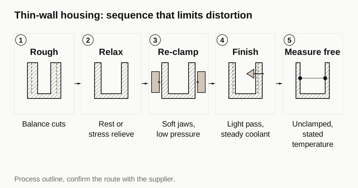
Cutting one side deep and the other side shallow unbalances the stress release. Shops rough both sides of a jacket in turn so that the part relaxes evenly, then leave a defined amount of material for finishing.
Separate roughing from finishing
This is the single biggest lever. The rough cut removes most of the stock and most of the stress. The part is then unclamped and allowed to relax, or given a stress relief cycle where the material allows it, and re-clamped lightly for the finish cut. The finish pass removes only a thin layer, so cutting force and heat are both small.
Cut light and sharp at the end
Finish passes use sharp tools with a positive geometry, a small depth of cut and a steady coolant flow. The aim is to push the wall as little as possible. Coolant temperature also matters, because a bore cut with warm coolant and measured in a cool room will not match.
Measure free, at a known temperature
The reading that counts is taken with the part unclamped and settled. Shops that machine thin-wall housings regularly check bore size and roundness on a gauge or CMM after a defined rest time, not at the machine with the clamp still closed.
What each cause costs you
| Cause | What it does to the part | Typical shop response | Effect on quote |
|---|---|---|---|
| Clamping force | Lobing, out of round bore | Soft jaws, mandrel, lower pressure | Fixture cost, setup time |
| Cutting force | Taper, size error | Light finish pass, sharp tools | Longer cycle |
| Heat | Size drift between cut and measure | Coolant control, rest before gauging | Waiting time per part |
| Residual stress | Slow shape change after cutting | Rough, relax, finish; stress relief | Extra operation |
| Gauging while clamped | False pass on a bad part | Free state measurement | Inspection time |
The pattern is simple. Every control adds a fixture, a step or a wait, and each of them shows up as time. A drawing that asks for tight roundness on a thin wall is asking for all five.
Drawing choices that help
You rarely get to change the wall thickness at the RFQ stage, but you can change how the drawing treats it.
- Ask for roundness only where the bearing needs it. Putting a tight roundness value on every cylindrical surface sends all of them through the slow route.
- State the measuring condition. Free state at 20 degrees C is a clear statement. A shop can then plan its rest time and gauging instead of guessing.
- Mark datum surfaces that are stiff. A flange face or a thick boss gives the shop a rigid place to clamp and to measure from.
- Allow a stress relief step if the material permits. Say so on the RFQ so that the shop does not have to ask or price it as a risk.
- Separate functional and cosmetic surfaces. A cooling fin face that nobody touches does not need the roundness of a bearing bore.
The guide to bearing fits and runout explains which of these callouts a bearing really responds to. The bearing seat fit reference lists bore limits by class.
Where roundness on a thin wall sits among the other housing callouts is covered in the motor housing tolerances guide.
Need a quote for this part? Get a quote for your motor part
Telling distortion from a bad program
When a bore comes back out of tolerance on a thin-wall housing, there are two possible causes with very different fixes. Either the machine cut the wrong size, or the part moved after a correct cut. The inspection pattern tells them apart.
- A bore that is the wrong size but round, and the same on every part, points to an offset or tool wear problem. It is a machine adjustment.
- A bore that is round while clamped and out of round when free, points to clamp lobing. It is a workholding problem.
- A bore that measures right on the day and drifts over days, points to residual stress or to a temperature difference between the cutting shop and the inspection room. It is a process route problem.
- A bore that is tapered, larger at the open end, points to wall deflection under the cutter. It is a finishing pass problem.
A shop that has seen all four will describe them in these terms. If the first reply to a failed part is “the tolerance is too tight”, ask which of the four patterns the measurements show.
Material notes
Aluminum jackets in 6061 or 6082 type alloys machine easily but move readily with heat. Steel shells move less with heat but carry forming stress from drawing or rolling. Cast housings add porosity as an extra risk once the wall is thin, because a thin wall has less material to hide a void in. Each combination has its own typical failure, and the shop’s choice of fixture follows from it. If the material is open to discussion at all, raise it before the RFQ closes. The buyer’s guide to housing and shaft machining describes the usual routes.
When the blank makes the difference
Some distortion is baked in before machining starts. A casting that has not been stress relieved or a bar that was cold straightened can move no matter how carefully it is machined. When a shop says it needs a different blank or a thermal treatment before machining, that is a process observation, not an excuse. Costs by blank type are in the guide to what drives housing machining cost.
Questions to ask a shop
- Which operations are done in the same clamping and which are separate?
- Is there a relaxation or stress relief step between roughing and finishing?
- How is the bore measured, when and at what part temperature?
- What was the highest scrap cause on a similar thin-wall part, and what changed afterwards?
- Is the fixture a cost to you or is it included?
A shop that answers these in specific terms has done the job before. A shop that answers in general terms may still do it well, but you will find out on the first article.
Checklist before you send the RFQ
- Give the wall thickness at its thinnest point and the unsupported length.
- State roundness and cylindricity only where the bearing needs them.
- State the measuring condition and temperature.
- Name the stiff surfaces that can serve as datums or clamp points.
- Say whether stress relief is allowed.
When the drawing is ready, send the RFQ and we quote the finished parts and place the work with a partner shop that machines motor parts, with replies within 24 business hours.
Standards and references
- Machining, overview of turning, milling and the forces involved. Background on cutting forces and heat, the two inputs behind thin wall movement.
- ISO 1101, Geometrical product specifications (GPS), Geometrical tolerancing. Defines roundness, cylindricity and runout, the callouts that thin walls put at risk.
- ISO 286-1, ISO code system for tolerances on linear sizes. The bore classes that a distorted wall can push out of limits.
Figures on this page are typical ranges drawn from the standards above and from ordinary shop practice. They are not a specification for your part. The partner shop that prices your part confirms what it can hold on your geometry.
Frequently asked questions
What wall thickness counts as thin for a motor housing?
There is no single cut off. What matters is the ratio of wall thickness to bore diameter and to unsupported length. A wall that is stiff on a short 80 mm housing can move on a 200 mm long jacket of the same thickness. If a shop raises distortion risk in a quote, ask which dimension worried it, because that is the one to discuss.
Should I specify roundness on the bearing bore of a thin-wall housing?
If the bearing needs it, yes, but state the value deliberately. A roundness limit tighter than the bearing manufacturer asks for makes the shop add a stress relief step and a slower finish pass. Check the bearing maker's housing requirements before copying a number from an older drawing.
Can a shop measure the bore while the part is still clamped?
It can, but that reading does not predict what the bore does when the clamp opens. A thin wall springs back. The check that matters is on the free part, on a gauge or CMM, at a stated temperature.
Need a quote for this part?
Send the drawing. We quote the finished parts, place the work with a partner shop and reply within 24 business hours.
Get a quote for your motor part