Guides / Tolerances
Stator Shrink Fit in a Motor Housing: How Interference and Roundness Work Together
Written by the team that reads your RFQPublished How we write these
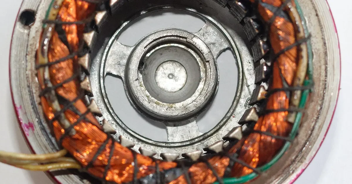
A stator core is a stack of thin steel laminations. Nothing glues it to the housing and nothing locks it with a key. In many motors the only thing holding it in place against the torque reaction is the grip of the housing bore, set up by shrink fitting. The bore therefore does a structural job, and the tolerance on it is a design requirement, not a convenience for the machine shop.
This guide explains the mechanics in plain terms, shows how to estimate the heat needed to assemble the fit and describes the bore callouts a buyer should put on the drawing.
What interference means here
Interference is the difference between the stator outside diameter and the housing bore diameter, with the bore smaller. A press or thermal assembly forces the two together, and the elastic grip that results holds the stator in place.
The amount is small compared with the diameter, often a few hundredths of a millimeter on a stator of 100 mm or so. Because the number is small, every deviation matters. If the finished bore is larger than drawn, the grip falls and the stator can turn under load. If it is smaller, the stator needs more force or more heat to assemble and the core takes more stress than designed.
That stress is not a minor point. Squeezing laminations changes how the steel behaves magnetically, and compressive stress raises core loss. Designers account for it when they choose the interference, which is one more reason the bore should land where the drawing says.
How a shrink fit is assembled
In a shrink fit the housing is heated so that the bore grows, the stator is dropped in or pushed in while the gap is open, and the housing cools and grips.
The temperature rise needed follows from thermal expansion:
Required rise = (interference + assembly clearance) / (expansion coefficient x bore diameter)
Aluminum alloys used for motor housings expand at roughly 23 micrometers per meter per kelvin. Steel expands at about half of that. Treat both as approximate, since the figure depends on alloy and temperature range.
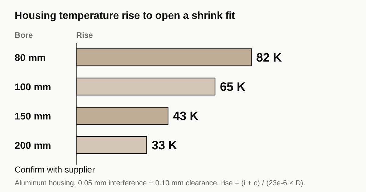
For a 0.05 mm interference and 0.10 mm of assembly clearance in an aluminum housing, the numbers work out as follows.
| Bore diameter | Rise needed above room temperature (approx.) |
|---|---|
| 80 mm | 82 K |
| 100 mm | 65 K |
| 150 mm | 43 K |
| 200 mm | 33 K |
These are worked examples from the formula, not recommended process settings. The real assembly temperature depends on the interference the designer chose, on how much clearance the line needs for a fast drop in and on limits such as seal and coating tolerance. Larger bores need a smaller rise for the same interference, which surprises people at first. The bore grows in proportion to its diameter, so a bigger bore opens more per degree.
Where roundness comes in
Size is only half the story. A bore that is the right average diameter but oval does not grip evenly.
- At the tight points the stator is squeezed harder than designed, with more core stress.
- At the loose points the grip is lower or absent, so the effective holding force falls.
The stator itself is not perfectly round either, because a laminated stack has small steps at the edges of each lamination. The stator and bore never mate perfectly, which is another reason to keep the bore form tight so the form error of the two parts does not add up.
How tight is tight? A common starting point is to keep roundness to a fraction of the interference, so that the grip stays within a narrow band around the design value. The fraction is a design decision. Ask the motor designer or the stator supplier, and state it on the drawing as a roundness or cylindricity tolerance with a measuring condition.
What the drawing should carry
For the stator bore, the drawing should state:
- Diameter with a tolerance class or limit values. H6 or H7 type classes are common for bores that need a controlled fit. The bearing seat fit reference lists limits for a given diameter.
- Roundness or cylindricity with a numeric limit. Leave it off and the shop works to its general tolerance, which is often looser than a shrink fit allows.
- Surface finish if it matters for grip. A very smooth bore can slide under load and a very rough one wears on assembly. The designer picks the range.
- Bore length and any chamfer at the entry. The lead in chamfer makes the stator drop in without catching.
- The measuring condition. Temperature at measurement and free state, with no clamp holding the part.
For the bearing seats, shoulders and mounting interface that sit around the stator bore, see the guide to motor housing tolerances.
What the machine shop controls
Shops that machine motor housings control the bore through a few practical steps.
- Finish boring in a separate light pass after the rough cut and after any stress relief, so cutting force and heat are small.
- Holding the housing on a stiff datum and not squeezing the wall, particularly on a thin-wall jacket. The related guide on machining thin-wall housings without distortion covers this in detail.
- Measuring the bore on the free part, at a stated temperature, with an air gauge or CMM and not a hand bore gauge alone.
- Checking roundness at more than one depth, since a bore can be round at the mouth and oval at the bottom.
Need a quote for this part? Get a quote for your motor part
Shrink fit, press fit and the alternatives
Shrink fitting is not the only way to seat a stator, and the choice changes what the housing drawing needs.
Press fit. The stator is pushed into a bore with a lead in chamfer, at room temperature, using a controlled press. The method suits steel and cast iron housings that would need a large temperature rise, and it needs a bore with a good entry geometry and a surface that does not scrape. Pressing can score the bore, so the finish and the chamfer matter more than on a shrink fit.
Shrink fit of the housing. The housing is heated and the stator drops in. This avoids scraping, and it suits aluminum housings well because they respond strongly to heat. It needs a safe temperature for any seal, coating or insert already in the housing.
Cooling the stator. Sometimes the stator is chilled instead of the housing heated, which gives a smaller effective change but protects the housing. It is less common on production lines, because the temperature swing available from cooling is limited compared with heating.
Bonded or keyed designs. Some motors add adhesive, a key or a retaining ring on top of a lighter interference. In those designs the bore tolerance is looser, but the extra features have their own callouts. A buyer should confirm which design applies before quoting, since the machining cost is different.
None of these choices is the machine shop’s to make. They are set by the motor design, and a drawing that makes the method clear removes a round of questions from the quoting stage.
A note on measurement
Bore size at the production line is checked many times a day, and a trend matters more than a single reading. A shop that logs bore diameter on every part, or on a regular sample, can show a drift before it becomes a reject. A drift of a few micrometers over a shift is normal as tools wear. Ask how often the tool offset is adjusted and what the action limit is. A shop that has a clear answer is controlling the process. A shop that says it checks every part but does not log the result is hoping.
Failure signs and their causes
| Symptom at assembly | Likely cause in the housing |
|---|---|
| Stator will not drop in at planned temperature | Bore under size or oval at the tight point |
| Stator drops in but spins under load later | Bore over size or interference too low |
| Core loss higher than the design value | Excess interference or uneven squeeze from oval bore |
| Housing bore changes between batches | Different heat or clamp conditions during finishing |
Not every symptom starts with the machining. A stator stack that is out of round or oversize gives the same signs, which is why the first check on a failing assembly is to measure both parts.
Design questions to settle before the RFQ
- What interference range does the design call for, and who set it?
- Is the housing aluminum, steel or iron, and does the assembly method suit it?
- Is there a cooling jacket or seal close to the bore that heat could damage?
- What bore roundness does the design tolerate?
- Is the stator supplied by the buyer, so that a fit trial can be done on sample parts?
If the answers are not yet known, say that on the RFQ and ask the shop to quote the bore at the class the designer has in mind. A trial fit of one housing and one stator on sample parts will settle most doubts before a production batch is cut.
Checklist before you send the RFQ
- State the bore diameter with limits and a numeric roundness value.
- State the measuring condition: free state at a stated temperature.
- Include the housing material and the assembly method the line will use.
- Mention any seal or coating near the bore that limits heating.
- Ask for the shop’s bore measuring method and for a first article report on the bore.
When the drawing is ready, send the RFQ and we quote the finished parts and place the work with a partner shop that machines motor parts. Replies come within 24 business hours.
Standards and references
- Interference fit, overview of press, shrink and expansion fits. Background on how interference holds a part without a key or fastener.
- Shrink fit, overview of the thermal assembly method. The heating and cooling idea behind section 2.
- ISO 286-1, ISO code system for tolerances on linear sizes. Source of the H and shaft class system used for bore size limits.
- ISO 1101, Geometrical product specifications (GPS), Geometrical tolerancing. Defines the roundness and cylindricity callouts.
Figures on this page are typical ranges drawn from the standards above and from ordinary shop practice. They are not a specification for your part. The partner shop that prices your part confirms what it can hold on your geometry.
Frequently asked questions
How much interference does a stator shrink fit need?
The motor designer sets it from the torque the fit must hold and the stress the core can tolerate. It is a design number, not a machining one, and it varies with stator diameter and housing material. What the machine shop controls is how closely the finished bore matches the number on the drawing.
Does the housing material change the shrink fit?
Yes. Aluminum expands roughly twice as much as steel for the same temperature rise, so an aluminum housing needs a smaller temperature increase to open up the same amount. A steel or cast iron housing needs more heat or a press fit instead.
Can a shop measure the bore before the stator goes in?
It should. The bore size and roundness are the two measurements that decide whether the fit holds, and they are much easier to check on an empty housing than to diagnose after the stator is pressed in.
Need a quote for this part?
Send the drawing. We quote the finished parts, place the work with a partner shop and reply within 24 business hours.
Get a quote for your motor part