Guides / Buyer Guide
Humanoid Robot Joint Actuator Housings: What to Specify Before You Ask for a Quote
Written by the team that reads your RFQPublished How we write these
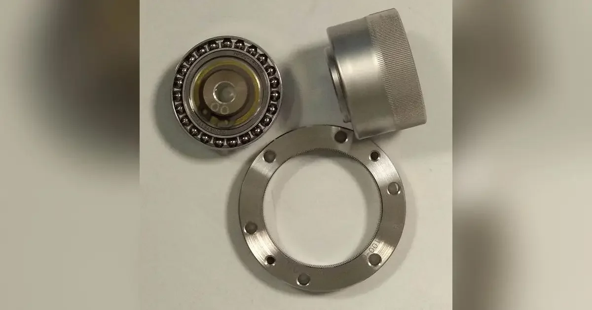
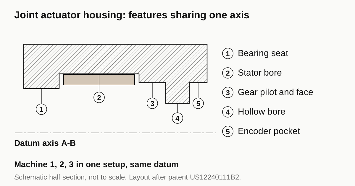
A robot joint actuator housing is a precision carrier, not a cover. It holds a frameless motor, a gear reducer and bearings on one axis. The features that decide whether the joint works are the bearing seats, the stator bore and the pilot that locates the gear, and the tolerance that matters most is how well they share one axis. A drawing that ties those features to a single datum gives you quotes you can compare. A drawing that does not gives you quotes that cannot be compared.
What sits inside a joint housing
One published layout, US patent 12240111B2, describes an actuator housing that defines the actuation axis. A frameless servo motor sits inside it with the stator fixed to the inner wall. A strain wave gear reduces the speed. The input and output shafts are hollow so cables can pass, several bearings carry the shafts and two encoders read the rotor and the output.
A strain wave gear has three working parts: a wave generator, which is an elliptical plug inside a bearing, a thin-walled flexspline cup with external teeth and a rigid circular spline ring with internal teeth. It fits ratios of 30:1 to 320:1 into the space where a planetary stage gives about 10:1 and it has no backlash, according to the overview on Wikipedia.
Not every humanoid uses one. Legged robots often prefer quasi-direct drive, where the gear ratio stays low so the joint can be backdriven. The MIT Cheetah paper builds its case on that idea and the NING humanoid reports three types of modular quasi-direct-drive actuators. The housing drawing differs between these layouts, but the logic is the same: motor, gear and bearings meet in one body.
| Housing feature | What it locates | Callout to expect |
|---|---|---|
| Bearing seats, input and output | Rotor and output shaft | Bore size class, roundness or cylindricity, coaxiality to the datum |
| Stator bore | Stator concentric to the rotor | Bore size class, roundness, coaxiality (see stator shrink fit) |
| Gear pilot and mounting face | Circular spline or gear housing | Pilot diameter, face squareness or runout to the datum axis |
| Cable bore | Hollow shaft clearance | Size limits and edge break |
| Encoder pocket | Magnet ring and sensing circuit | Position and depth to the datum |
| Flange and bolt circle | Joint to link structure | Hole position, face flatness |
Why one axis matters more than any single size
The flexspline is a thin cup that the wave generator flexes into an ellipse. If the gear pilot and the bearing seats are not on one axis, the mesh loads unevenly around the circumference. That is engineering reasoning rather than a quoted rule, but it explains why gear makers publish mounting tolerances by size and why joint designers copy them. This article does not print those values. They differ by gear size and revision, so take them from the current catalogue for your model and put them on the housing drawing.
What a buyer can check is how the bores are made. ZEISS lists three causes of lost coaxiality: faulty clamping of the workpiece, a tool holder that yields and machine vibration. Each points to the same practice. Bores and faces that must share an axis belong in one setup, or in a second setup that is located from a datum feature the shop has already measured.
Size classes still matter. For a 60 mm bearing seat the ISO 286 widths are 13 micrometers at IT5, 19 at IT6 and 30 at IT7. Those numbers describe the diameter only. A bore can be inside its size class and still sit off the axis. The bearing fit reference gives limits for a given diameter and the guide on bearing fits, concentricity and runout explains how the three controls differ.
Material and thermal growth
The NING humanoid paper reports that most parts are aluminum 7075 and that the key stress components are machined from high stiffness steel. Aluminum saves weight. The cost is differential growth against the steel bearings and gear parts that sit in the housing.
A worked example shows the size of it. Take a 60 mm bearing seat in an aluminum housing, holding a steel bearing outer ring. The linear expansion coefficients at 20 degrees C are 23.1 for aluminum and 10.8 for carbon steel, in units of 1e-6 per kelvin. For a 40 K temperature rise:
- Aluminum bore grows 60 x 23.1e-6 x 40 = 0.055 mm.
- Steel ring grows 60 x 10.8e-6 x 40 = 0.026 mm.
- The fit opens by about 0.030 mm, which is the full IT7 band for that size.
This is arithmetic, not a design rule. The designer chooses the interference with the temperature range in mind. For the shop it means the bore size must land where the drawing says, because there is little margin to absorb an error.
State the alloy and the temper on the drawing, for example 7075 in a named temper, and say whether the part is anodized. Coating changes the finished size, so say whether bore dimensions apply before or after it. The guide to anodize, e-coat or powder coat covers the options.
Need a quote for this part? Get a quote for your motor part
What changes the quote
No public shop-rate survey exists for robot actuator housings, so compare quotes on the same drawing instead of on a rule of thumb. The points below are where quotes usually separate:
- Setups. One setup for the bores and faces costs more machine time per part but protects the axis. Several setups cost less and need a stated locating method.
- Thin walls. Light housings have thin sections that move when clamped or when stress releases. The guide on thin-wall housing machining lists the common controls.
- Measurement. Coaxiality is now measured almost entirely digitally with optical or tactile sensors, per ZEISS. Ask for a first article report that lists the coaxiality values and the datum set up used.
- Blank. Billet suits prototypes and low volume. A casting or forging blank lowers cost at volume and adds a lead time. The article on billet prototypes before die casting tooling explains the trade.
Features buyers forget to call out
Quotes go wrong less often on the big bores than on the small features around them. Five are worth a line on the drawing:
- Encoder pocket. The magnet ring and the sensing circuit have to sit at a stated distance from each other and on the datum axis. A pocket machined to a general tolerance can shift the reading.
- Cable bore edges. The hollow shaft path carries wiring. Say what edge break the bore needs so insulation is not cut when cables are pulled through.
- Seal and groove geometry. If the joint is sealed, give the groove size and the surface finish of the sealing face. The guide on pump and compressor end bells covers sealing fits.
- Mass target. Weight drives the whole design. The NING humanoid stands 1.1 meters tall and weighs 20 kg, so every housing is part of a tight mass budget. If lightening pockets or thin ribs are in the design, flag them, because they decide how the part is held.
- Mounting flange. Hole position and face flatness set how the joint attaches to the link. Give a position value to the datum axis instead of a plain hole size.
Where a small drone or robot motor sits inside the joint rather than a frameless kit, the guide on small BLDC housings for drones and robotics covers the lighter parts.
Checklist before you send the RFQ
- Drawing with the bearing seats, stator bore and gear pilot tied to one datum axis.
- Numeric coaxiality or runout values for those features, copied from the gear and bearing catalogues where they apply.
- Alloy, temper and finish, with a note on whether dimensions apply before or after coating.
- Bore size classes and the temperature at which they are measured.
- Quantity for the prototype and the expected yearly volume.
- The inspection report you want with the first article.
Once the drawing carries these items, send the RFQ. We quote the finished parts and place the work with a partner shop that machines motor parts, and reply within 24 business hours.
Standards and references
- US12240111B2, Robotic joint actuator. One published layout: frameless motor, strain wave gear, hollow shafts and encoders inside a single housing.
- Strain wave gearing, overview. Wave generator, flexspline and circular spline, and the 30:1 to 320:1 ratio range.
- Wensing et al., Proprioceptive Actuator Design in the MIT Cheetah (IEEE Transactions on Robotics, 2017). Why legged robots use backdrivable, low-ratio actuators.
- The NING Humanoid, concurrent design and development of a dynamic and agile platform (arXiv 2408.01056). A humanoid built with quasi-direct-drive actuators, most parts in aluminum 7075.
- Thermal expansion, table of linear coefficients at 20 degrees C. Aluminum 23.1 and carbon steel 10.8 in 1e-6 per K, used in the worked example.
- IT Grade, table of ISO 286 tolerance grades. IT5, IT6 and IT7 widths for the 50 to 80 mm size range.
- ZEISS Metrology, Coaxiality. Causes of lost coaxiality and how it is measured.
Figures on this page are typical ranges drawn from the standards above and from ordinary shop practice. They are not a specification for your part. The partner shop that prices your part confirms what it can hold on your geometry.
Frequently asked questions
What are the critical features of a robot joint actuator housing?
The bearing seats, the stator bore and the pilot and face that locate the gear, plus how well all three share one axis. Cable bore, encoder pocket and mounting flange follow. Tie the first three to a single datum axis on the drawing so every shop quotes the same requirement.
Which material do humanoid joint housings use?
Published designs vary. The NING humanoid paper reports most parts in aluminum 7075 with high stiffness steel for the key stress parts. Your choice depends on weight target, stiffness and the thermal growth against the steel bearings and gear, so state the alloy and temper on the drawing.
Does the gear maker set the housing tolerances?
Usually the gear and bearing makers publish recommended mounting tolerances by size, and the joint designer adopts them. Copy the values for your exact model from the current catalogue onto the housing drawing. A shop cannot guess them, and they change with size and revision.
Is a robot actuator housing machined from billet or cast?
Low volume housings are usually turned and milled from billet or bar. Higher volumes can start from a casting or forging blank, with the same bores and faces machined afterwards. The choice follows quantity and shape, and the finished tolerances on the bores stay the same either way.
Need a quote for this part?
Send the drawing. We quote the finished parts, place the work with a partner shop and reply within 24 business hours.
Get a quote for your motor part