Guides / Buyer Guide
Knurled or Keyed Rotor Shaft: How the Lamination Stack Is Held and What the Drawing Must Say
Written by the team that reads your RFQPublished How we write these
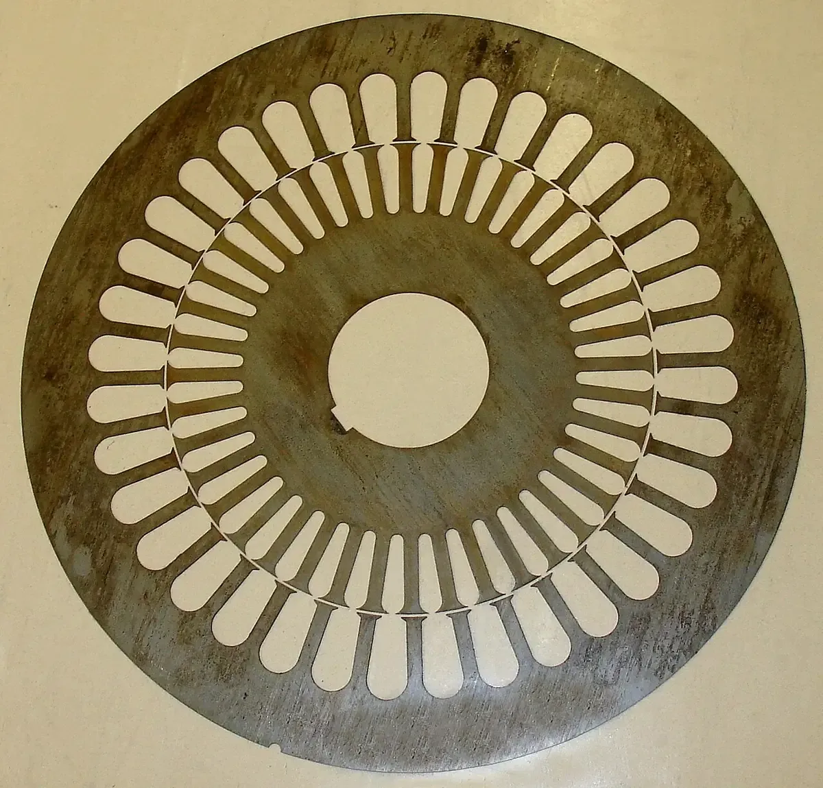
Which method holds the lamination stack on a rotor shaft is the rotor designer’s call, and no public standard picks one. For a buyer, the useful question is what each method adds to the shaft drawing and to the quote. A knurled press fit adds a rolling operation and a diameter over the ridges to control. A key adds a keyway to mill and a balance convention to agree. A shrink fit adds heat and an axial position to guard. Axial clamping adds thrust washers and a fixture. Pick the method before you request quotes, or the shaft prices will not be comparable.
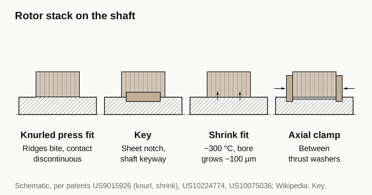
Four ways to hold the stack
| Method | Torque path | Effect on the laminations | Added work on the shaft |
|---|---|---|---|
| Knurled press fit | Friction plus ridge engagement | Ridges give discontinuous contact, each sheet can deflect, less residual stress and scratching | Knurling pass, diameter over ridges to control |
| Key | Positive stop in the keyway | Every sheet needs a matching notch | Keyway milled or shaped, balance convention |
| Shrink fit | Friction from heating the stack | Conventional method heats to about 300 degrees C, the bore grows about 100 micrometers, axial drift of about 2 mm between products | Close diameter control, shoulder for axial position |
| Axial clamp | Friction from clamping force between thrust washers | No interference on the stack bore, so no stress at the bore | Two enlarged sections for washers, fixture and force control |
The wording comes from three patents. They describe design intent and claimed benefit. They are not test reports, so none of them proves one method is better than another. They are useful because they state what each method is trying to avoid.
What a plain press fit costs the laminations
US10224774 lists the drawbacks of a frictional press fit: the electromagnetic performance of the sheets is impaired at the joining diameter, and stresses from the interference fit can degrade the magnetic properties of the electrical steel and damage brittle magnets embedded in the stack. US10075036 adds two mechanical problems: the press-fit allowance sets the rotating torque, so reducing it to limit deformation also reduces torque, and galling between core and shaft raises the press-in force.
That is the reason for the other methods. Knurling keeps the friction path but reduces how much of the bore is in contact at one time. The knurled design in US9015926 makes discontinuous contact so that each sheet can deflect toward the stack axis, which the patent says avoids residual stress and scratches. The knurled ridges also appear in US10075036 as a way to enlarge the press-fit area on a shorter core.
Shrink fit and its side effects
The shrink fit in US9015926 is the conventional alternative. The stack is clamped between plates, heated to about 300 degrees C, and its bore expands by roughly 100 micrometers, so the shaft slips in and the stack grips as it cools. The patent reports that residual stress pushes the stack axially, with variation of about 2 mm between products. An axial offset moves part of the stack out of line with the stator, which reduces output. For the shaft drawing the lesson is to define the axial seating shoulder and ask how the stack is held while it cools.
Keys
A parallel key is the most widely used type according to the Wikipedia entry, with a square or rectangular section. The entry also notes that improperly machined keyways, for example with cutter deflection, may not be strong enough, and that a Woodruff key avoids milling near shaft shoulders where stress concentration and concentricity suffer. The guide on shaft splines and keyways compares the cutting processes.
Two consequences follow for a motor rotor. The key has to be accommodated in the lamination too, so the sheet has a notch, as in the photograph above. And the key takes mass off one side of the shaft. How the key counts during balancing is a convention that has to be named on the drawing, as the rotor balancing guide explains.
Axial clamping
US10224774 describes a stack that sits with clearance on the shaft and is held only by friction between two thrust washers. Both washers are pressed onto shaft sections that have been enlarged by roller burnishing, so no key, adhesive or interference fit is needed on the stack bore. The patent gives no force, torque or dimension, so there are no numbers to copy. For the buyer it shows that “knurled or keyed” is not the only choice, and that roller forming of the shaft surface appears here as well.
Need a quote for this part? Get a quote for your motor part
Choosing between them
The opened sources give four triggers that push the designer one way or the other.
- Magnets embedded in the stack. US10224774 says interference stress can damage brittle magnets. That points away from a heavy plain press fit, toward knurling or axial clamping.
- Axial position matters. The shrink fit in US9015926 drifts by about 2 mm between products. If the stack must line up with the stator, the drawing needs a seating shoulder and a stated process.
- Shock or overload. A key is a positive stop, but a keyway is also a stress raiser in the shaft, and the Wikipedia entry warns about badly machined ones. A designer who expects shock loads weighs both.
- Cost of the operation. Each method adds one operation. Knurling is a rolling pass, a keyway is a cutting operation and clamping needs two enlarged sections. Only quotes on your drawing show which costs less.
Drawing a knurled section
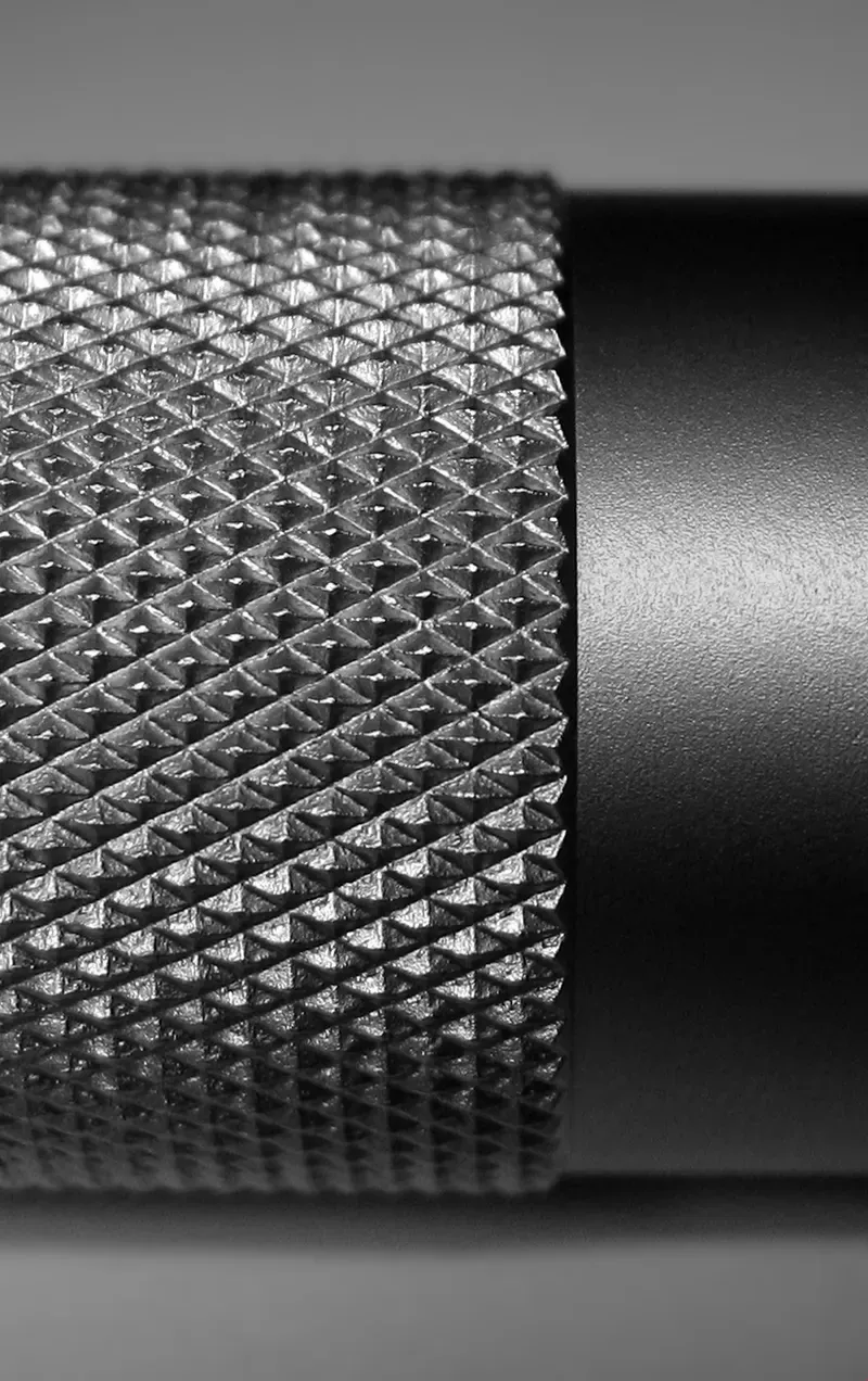
Knurling is a forming process. The Wikipedia entry describes a pattern of straight, angled or crossed lines rolled into the material, and a source quoted there describes the effect as displacement of the material. Raised ridges mean the diameter over the knurl is larger than the diameter before it, so a drawing that says only “knurl Ø20” is ambiguous. Put these items on it:
- The pattern, straight or diamond, and the pitch.
- The axial position and length of the knurled band, with the datum from the seating shoulder.
- The diameter before knurling and the diameter over the ridges, with a tolerance on each.
- How the diameter over the ridges is measured, since a micrometer touches the ridge tips.
- A note on the finishing order, for example journals finished after the forming step. The grinding versus hard turning guide covers journal finishing.
- Whether the ridge ends may protrude past the core end face. One claim in US10075036 keeps them inside.
No public source gives a standard interference or knurl depth for motor rotors, and none is printed here. The rotor designer sets them from torque and speed, and the lamination bore has to be tolerated to match.
What to ask a shop
- Which operation order they will use: turn, knurl, grind, or knurl last.
- How they check straightness after the forming pass.
- Whether the key convention is full key, half key or no key for balancing.
- Whether the shaft is hollow, since forming a hollow shaft is a different job, see hollow rotor shafts.
When the drawing is ready, send the RFQ and we quote the finished parts and place the work with a partner shop that machines motor parts, with a reply within 24 business hours.
Standards and references
- US10075036B2, Rotor for rotary electric machine having ridge-shaped convex and concave portions to secure a press-fitted shaft. Press fit torque against waviness and galling, with knurling used to increase the press-fit area.
- US9015926B2, Method for producing a motor rotor. Knurled shaft with discontinuous contact, and the conventional shrink fit with its temperature, bore growth and axial drift.
- US10224774B2, Rotor shaft with a laminated core. Prior art on press fit, shrink fit, keys and clamping, and a stack held between thrust washers on roller-enlarged shaft sections.
- Knurling, overview. A rolled pattern, straight and diamond types, material displaced rather than cut, one example pitch.
- Key (engineering), overview. Parallel and Woodruff keys, keyway machining and stress concentration.
Figures on this page are typical ranges drawn from the standards above and from ordinary shop practice. They are not a specification for your part. The partner shop that prices your part confirms what it can hold on your geometry.
Frequently asked questions
What is a knurled rotor shaft?
A shaft with a rolled pattern of raised ridges on the section where the lamination stack sits. The stack is pressed on, and the ridges bite into the bore. The Wikipedia entry describes knurling as displacing material, which raises the diameter over the ridges, so the drawing must say which diameter counts.
Is a knurled press fit stronger than a key?
No public standard ranks them. A key gives a positive mechanical stop and a knurled fit relies on friction and ridge engagement. One patent describes the knurled fit as avoiding residual stress and scratches. The rotor designer decides, using torque, speed and service needs.
Does a tight press fit damage the laminations?
It can. US10224774 states that stresses from an interference fit can degrade the magnetic properties of the electrical steel sheets and damage brittle magnets embedded in the stack. That is why designers use relieved bores, knurling or axial clamping instead of a plain heavy fit.
What should the shaft drawing show for a knurled section?
The pattern and pitch, the axial length and position of the knurl, the diameter before knurling, the diameter over the ridges and how it is measured. Add the datum the stack seats against and the finishing order.
Need a quote for this part?
Send the drawing. We quote the finished parts, place the work with a partner shop and reply within 24 business hours.
Get a quote for your motor part