Guides / Cost
Hollow Rotor Shafts: Seamless Tube or Gun-Drilled Bar?
Written by the team that reads your RFQPublished How we write these
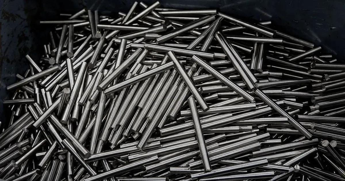
A solid shaft carries torque with metal that it does not need. The material in the middle contributes little to bending strength and torsional stiffness for its weight, so designers hollow it out when mass matters or when something has to pass through. Electric traction motors use hollow shafts to carry cooling oil to the rotor. Servo and direct drive motors use them for cables and sensors. The question for the buyer is how to make the hole.
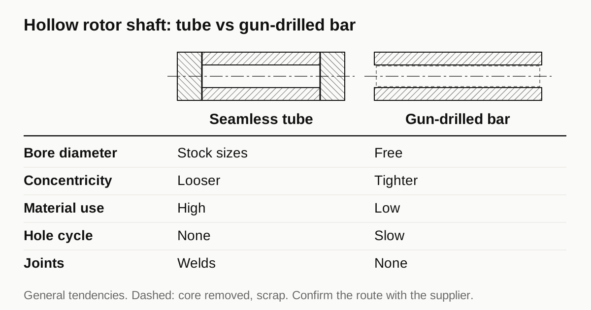
There are two main routes. This guide compares them, explains where each wins and lists what the drawing should say.
Why a shaft goes hollow
- Mass reduction. A hollow section keeps most of the bending stiffness for far less weight. Lower rotor inertia also helps acceleration in servo drives.
- Cooling. Oil or coolant pumped through the shaft carries heat away from the rotor, which is hard to cool from outside.
- Pass-through. A wire, a sensor rod or a torque tube sits inside the shaft.
- Stiffness to weight. For a given mass, a larger diameter hollow shaft is stiffer than a smaller solid one.
The reason sets the bore. A cooling bore carries a flow that needs a minimum diameter. A weight bore can be as large as the wall strength allows. A pass-through bore is sized to the part it carries.
Route one: seamless tube
A seamless steel tube is made by piercing a billet and rolling or drawing it to size, with no weld seam. Mechanical tubing comes in hot finished and cold drawn forms. Standards such as EN 10297-1 define the dimensions, tolerances and steel grades.
How the shaft is made from it. The tube is cut to length, the outside is turned to the shaft profile, journals are finished and ends are prepared. Often the tube is only the middle section, and solid end stubs are joined to it by friction welding, laser welding or an interference fit.
Strengths
- The bore comes with the stock, so no deep drilling.
- Material cost is low for standard sizes.
- Lead time is short when the size is stocked.
Limits
- Sizes are standardized. A bore diameter that is not on the list needs a special order or a different route.
- Wall thickness varies. The bore and the outside are not perfectly concentric in stock tube, so turning the outside to size leaves a wall that is thicker on one side. For a rotating shaft, this adds unbalance.
- The inside surface is as rolled or drawn, not as machined. If the bore needs a finish or a size tolerance, it needs an extra operation.
- Joining stubs to the tube adds a weld or a fit, and each is a critical step.
Route two: gun-drilled bar
A gun drill is a long single flute drill that is fed with coolant through the tool at high pressure. It cuts a deep, straight, round hole in solid bar with a good finish and a small wandering of the hole.
How the shaft is made from it. Bar of the right grade is cut to length, rough turned and gun drilled from one or both ends. The shaft is then finished in the usual way.
Strengths
- Any bore diameter within the drill range is possible.
- The bore position is set by the machine and is controlled against the outside, so wall thickness is even when the shop gets the setup right.
- Blind holes, stepped bores and holes with a controlled exit are possible.
- It is one piece, so no welds or joints.
Limits
- It is slow. Gun drilling removes material at a modest rate, so a long hole takes minutes.
- Tooling is specific to each diameter and costs money.
- Hole straightness drifts with depth. Drift at the exit relative to the entry is a characteristic of the process and is a drawing item for long shafts.
- Material waste is high, since the drilled core is scrap.
Side by side
| Factor | Seamless tube | Gun-drilled bar |
|---|---|---|
| Bore diameter choice | Limited to stock sizes | Free within drill range |
| Wall concentricity | Depends on tube quality, often looser | Controlled by setup, usually tighter |
| Material utilization | High | Low |
| Cycle time for the hole | None | Slow |
| Joints or welds | Often needed for stubs | None |
| Typical best fit | Standard bore, volume, lower precision | Custom bore, tight wall, blind or stepped holes |
These are general tendencies. Real cost depends on the shaft length, the bore and the quantity, so ask for both quotes where the design allows both.
Concentricity and balance
The most important quality for a hollow rotor shaft is the wall. A wall that is thick on one side is a heavy spot, and the rotor will not balance without correction. Concentricity of the bore to the outside therefore matters for both routes.
On tube stock, ask the supplier for the ID and OD concentricity tolerance and whether the shaft outside diameter is turned from the tube centerline or from the bore. On gun-drilled bar, ask how the bore position is controlled and what exit drift to expect on the length you need. The balancing guide explains why concentricity matters to the final result, and the guide to bearing fits and runout covers the journals.
Joining stubs to a tube
Many hollow shafts are built from three pieces: a tube in the middle and a solid stub at each end that carries the journal, the spline or the flange. The joint then becomes a critical feature.
- Friction welding spins one part against the other under pressure until the interface heats and fuses. It makes a strong, clean joint with a small flash that is machined off. It suits round sections of similar size.
- Laser or electron beam welding gives a narrow weld with low heat input and little distortion. It suits thin walled tubes and is common in EV rotor shafts.
- Interference or threaded joints hold the stub with a press fit or a thread plus a seal. They are simple but carry less torque per size.
Whichever joint is used, the shaft is finish machined after joining, so that journals and seats run true to each other. The weld zone has its own heat treatment effect. A shaft that was hardened before welding may soften next to the joint, so the order of heat treatment, welding and finishing has to be planned. A buyer who sees a welded shaft quote should ask where the joint sits relative to the journals and how it is inspected, for example by ultrasonic test or by a section on a sample.
Need a quote for this part? Get a quote for your motor part
Cross holes and oil passages
Hollow shafts that carry oil usually have cross holes that feed the rotor. Their position, size and edge quality affect both flow and fatigue.
- Edge condition. A burr at the intersection of a cross hole and the main bore breaks off in service and travels with the oil. Deburring inside a deep bore is a real task, with tools such as abrasive flow, thermal methods or cross hole brushes.
- Stress concentration. A cross hole in a shaft is a stress raiser. Designers radius or chamfer the edge, and the machine shop has to hold the shape.
- Cleanliness. Chips and cutting fluid left in a long bore end up in the motor. A cleanliness specification, often by weighing particles from a flush, is part of the order for oil cooled shafts.
These steps add cost that does not show on a simple shaft quote. If the drawing includes oil passages, make sure the RFQ states the cleanliness requirement and how it is checked, since a shop that sees a hole and a diameter may not price the cleaning.
Heat treatment of hollow shafts
Hollow shafts behave differently in heat treatment from solid ones. A thin wall heats and cools faster, which can change the hardness and the distortion pattern. Quenching a long tube can bend it or make it oval. The designer may call for through hardening on thick walls, induction hardening on the journals only or no hardening at all and a high strength alloy instead.
The guide to induction hardened journals describes localized hardening, which suits hollow shafts well because it keeps heat in the journal zone and leaves the rest of the tube stable.
Finishing the bore
A bore for a seal, a plug or a press fit needs a defined diameter and surface. Options after drilling or tube forming include:
- Boring for a controlled size with good concentricity.
- Honing for fine size and surface finish and good straightness.
- Skiving and roller burnishing for a smooth surface with less material removal.
- Reaming for short holes.
Cooling bores often carry no tolerance beyond a minimum diameter and a clean surface. Plug seats and press fits need real limits. State which parts of the bore carry limits and leave the rest at a general tolerance.
What the drawing should state
- Bore diameter, tolerance and length of each section.
- Concentricity or wall thickness variation of the bore to the outside.
- Whether the bore is through or blind and the shape of the end.
- Surface finish where it matters, and cleanliness for oil passages.
- Material grade and heat treatment.
- Cross holes, with position and deburring requirements.
- How stubs are joined, if used, with the weld or fit standard.
Questions to ask a shop
- Which route do you recommend for this length and bore, and why?
- What exit drift or wall variation do you expect?
- How do you deburr cross holes inside the bore?
- How do you check cleanliness of an oil passage?
- Are welded stubs acceptable, and which process do you use?
Checklist before you send the RFQ
- State why the shaft is hollow, so the shop knows which tolerance matters.
- Show the bore with limits only where needed.
- State wall thickness variation or concentricity.
- Say whether welded construction is allowed.
- Give quantity, so tube and gun drilling can be compared fairly.
When the drawing is ready, send the RFQ and we quote the finished parts and place the work with a partner shop that machines motor shafts, with replies within 24 business hours. The cost guide lists the other drivers.
Standards and references
- Gun drilling, overview of deep hole drilling. How gun drills cut deep, straight holes and why the process is slow but accurate.
- Machining, overview of turning, drilling and related processes. Background for the finishing operations described here.
- EN 10297-1, Seamless circular steel tubes for mechanical and general engineering purposes. Dimensions, tolerances and grades of the tube route. Check the current edition.
- ISO 286-1, ISO code system for tolerances on linear sizes. Bore and journal classes referred to throughout.
Figures on this page are typical ranges drawn from the standards above and from ordinary shop practice. They are not a specification for your part. The partner shop that prices your part confirms what it can hold on your geometry.
Frequently asked questions
Why make a rotor shaft hollow at all?
Common reasons are lower mass, a path for coolant or oil down the shaft, space for a sensor or a wire and a better stiffness to weight ratio. Each reason leads to a different bore size and a different tolerance, so say which one applies.
Which is cheaper, tube or gun-drilled bar?
Tube is often cheaper when a standard size matches the design, because the bore is already there. Gun drilling wins when the bore size or position is not available in a tube, when the hole is not through, or when tight wall concentricity is needed.
Can the tube and the bore be both finished to a tight tolerance?
Yes, with extra work. Tube stock is made to a mill tolerance, so a tight bore needs honing or boring after, and the outside is turned or ground. The extra steps are what the quote differences usually reflect.
Need a quote for this part?
Send the drawing. We quote the finished parts, place the work with a partner shop and reply within 24 business hours.
Get a quote for your motor part