Guides / Tolerances
Rotor Balancing: What G2.5 and G6.3 Mean on a Motor Drawing
Written by the team that reads your RFQPublished How we write these
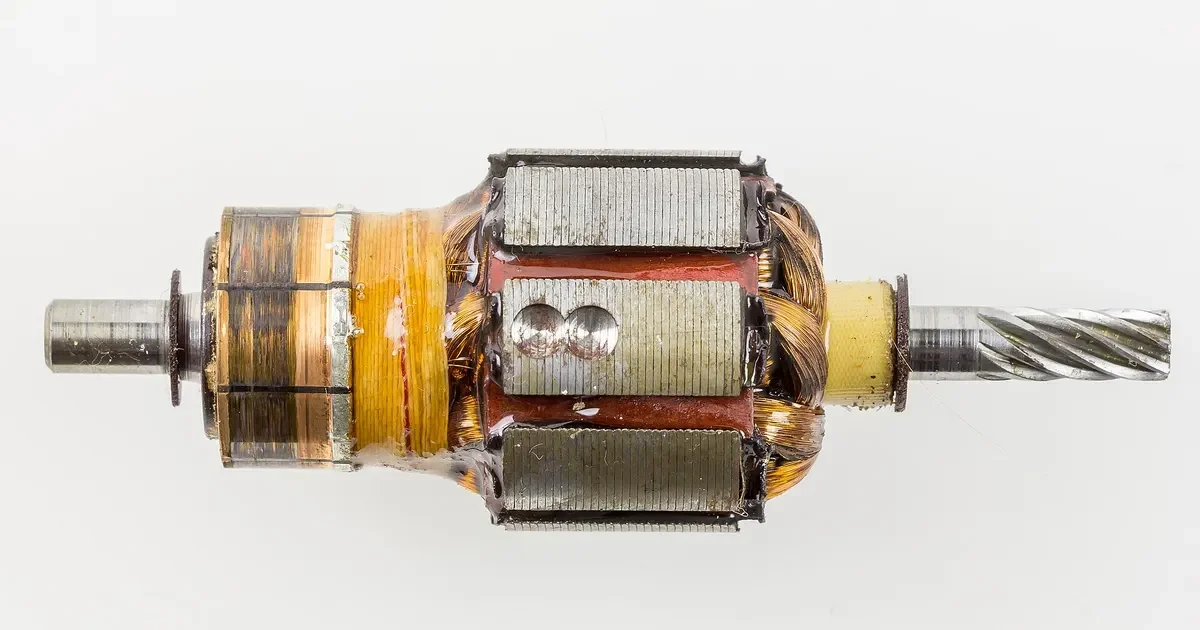
A balance grade on a motor drawing is one short code, G2.5 or G6.3, and it reads like a quality level. It is more precise than that. Each grade limits how much of the rotor’s mass can sit off its rotation axis, and the limit shrinks as speed rises. Turning the code into a number of grams and millimeters is what lets a buyer and a shop agree on what is being asked.
This guide explains the grade system in plain terms, works a few numbers and shows what to write on a drawing and on an RFQ. The site also has a rotor balance grade calculator that does the arithmetic for a chosen speed and mass.
What a G grade is
The G number comes from ISO 21940-11, which replaced the older ISO 1940-1 and carries the same grade system. A grade is the product of two quantities: the allowed eccentricity of the rotor’s center of mass, and the angular speed of the rotor.
G = permissible eccentricity x angular velocity, expressed in millimeters per second.
A rotor with a G2.5 grade can have an eccentricity multiplied by angular speed of up to 2.5 mm/s. At a higher speed the permissible eccentricity falls in proportion. This is the useful property of the system, since it keeps the force from unbalance roughly comparable across rotors of the same grade.
The arithmetic
With speed n in revolutions per minute, the permissible eccentricity in micrometers is:
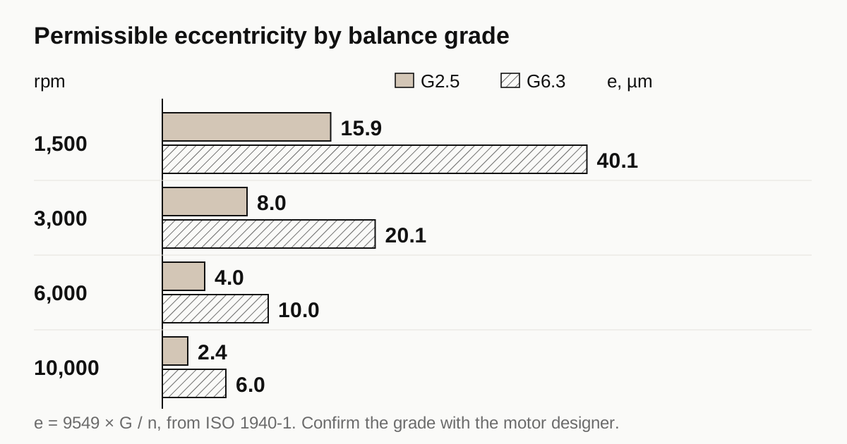
e = 9549 x G / n
The permissible residual unbalance in gram millimeters is e multiplied by the rotor mass in kilograms:
U = e x m
A worked table for G2.5 and G6.3 at four speeds follows.
| Speed | G2.5 permissible eccentricity | G6.3 permissible eccentricity |
|---|---|---|
| 1,500 rpm | 15.9 micrometers | 40.1 micrometers |
| 3,000 rpm | 8.0 micrometers | 20.1 micrometers |
| 6,000 rpm | 4.0 micrometers | 10.0 micrometers |
| 10,000 rpm | 2.4 micrometers | 6.0 micrometers |
For a 2 kg rotor at 3,000 rpm, G2.5 allows about 16 g.mm of residual unbalance in total, and G6.3 allows about 40 g.mm. If the rotor is balanced in two planes, the total is normally shared between them, often half each for a rotor with its center of mass midway between the planes. ISO gives the exact rule for other layouts.
These are results from the standard’s formula, not machining tolerances. They show how small the numbers get. A few micrometers of eccentricity is the size of a good journal runout, which tells you why balance and runout are related.
Which grade for which motor
The standard lists typical grades by machine type. General figures, to be confirmed against the current edition, run along these lines.
- G6.3 is common for general purpose electric motor rotors, fans and pump impellers.
- G2.5 is common for motors with higher speed or tighter noise and vibration needs, including many servo and machine tool drives.
- G1 and below show up in precision spindles and special applications.
The right grade for a given motor is the designer’s decision. It reflects speed, bearing type, mounting stiffness and acceptable vibration. A buyer should not change a grade to save money without the motor designer’s agreement, because the effect shows up in noise and bearing life, often only after a few months of use.
What a balance callout applies to
A balance grade applies to a rotor in a defined state. That state matters.
- The rotor includes everything that spins with it: shaft, core, magnets, retaining parts, fan and sometimes a half key. ISO 21940-32 sets the key convention, so check whether the drawing balances with a full key, a half key or no key.
- A callout on a bare shaft is a different job. It limits the shaft’s own unbalance before assembly, and the finished rotor is balanced again later.
- A housing or end bell does not rotate, so a balance callout on it has no meaning. A shop may quote it anyway and charge for a step that does nothing.
If a drawing states a grade for a part, ask what state it applies to.
Who does the balancing and how
Balancing is done on a balancing machine that spins the rotor on its journals or on support rollers and measures the force at each end. The operator then corrects the rotor by removing or adding mass at known radii, then spins it again to confirm.
Removing mass means drilling, milling or grinding small amounts from the rim of a lamination end ring or a balance land on the shaft.
Adding mass means clips, putty or screws at set positions on the end rings.
The choice depends on rotor design. Magnet rotors often balance by drilling a defined balance land. Cage rotors may use end ring correction.
In most supply chains the motor builder does this step on the finished rotor. A shaft supplier who machines the shaft can help by holding journal runout and keeping the shaft mass symmetric, which leaves less for the balancer to correct. The guide on bearing fits and runout shows how runout feeds balance.
Static and dynamic unbalance
Unbalance comes in two forms, and the difference decides whether one correction plane is enough.
Static unbalance is a single heavy spot. The rotor’s center of mass sits off the axis, so a rotor placed on level knife edges rolls until the heavy side is down. One correction plane can fix it.
Couple unbalance is two equal heavy spots on opposite sides at opposite ends. The center of mass can sit exactly on the axis and the rotor still rocks when spun, because the two spots create a turning moment on the bearings. It takes two planes to fix.
Dynamic unbalance is the general case, a mix of both. Most real rotors have it, which is why longer rotors are balanced in two planes.
A short disc shaped rotor, narrow compared with its diameter, is often balanced in one plane. A long rotor needs two. The drawing should say which, since it changes the machine setup and the time per part.
Need a quote for this part? Get a quote for your motor part
How shaft machining affects balance
A shaft machine shop does not balance the finished rotor, but its work moves the balance result in four ways.
- Journal runout. If the bearing journals do not share an axis with the rotor seat, the rotor spins about a line that is not its geometric axis, and the balancer sees eccentricity.
- Seat concentricity. The surface that carries the laminations or magnets has to run true to the journals, or the stack sits off axis.
- Mass symmetry. Keyways, flats, cross holes and spline ends take mass from one side. A single keyway on a shaft is the usual example, and it is why the key convention matters.
- Straightness. A bent shaft turns an ordinary rotor into an unbalanced one, and straightening after heat treatment is a normal step on slender shafts.
Shops that make motor shafts for a living hold the first two tightly because they know the balancer will find them. Ask the shop for a runout report on the journals and the rotor seat, measured between the journals.
What can go wrong
| Problem | What it looks like | Typical cause |
|---|---|---|
| Rotor passes at the balancer and runs rough in the motor | Vibration after assembly | Fit between shaft and rotor shifts, or balance done without the fan or key |
| Residual unbalance varies between rotors | Scatter in readings | Journal runout or shaft seat varying from shaft to shaft |
| Correction needs a lot of material | Deep drilling on every rotor | Large systematic error in the shaft or stack, not random unbalance |
| Rotor needs two correction passes | Long cycle time | Tight grade combined with large initial unbalance |
| Balance changes after a few weeks | Noise comes back | Parts settle or fasteners relax after the first run |
If every rotor needs heavy correction on the same side, the problem is not the balancer. Something systematic in the shaft or the assembly puts mass in the same place each time, and fixing that is cheaper than drilling every rotor.
What shapes the cost of balancing
- The grade. Tighter grades need a better machine, tighter setup repeatability and sometimes two correction passes.
- One plane or two. Two plane balancing costs more time.
- Rotor length compared to diameter. Long thin rotors behave differently at speed and may need two planes.
- Correction method. Drilling is quick. Complex correction costs more.
- Inspection record. A certificate with measured residual unbalance takes time to print and check.
Writing the callout
State all of the following, and the shop can quote without guessing.
- Grade, such as G2.5 or G6.3, and the standard edition.
- Service speed in rpm. The grade acts at that speed.
- The state of the rotor: with or without a key, fan and magnets.
- Number of correction planes.
- Where correction mass may be removed or added.
- Whether a record of residual unbalance is required.
Checklist before you send the RFQ
- Confirm that the balance step belongs to the supplier you are quoting.
- Write the grade, speed and rotor state together.
- Allow a place for correction on the drawing.
- Ask for the residual unbalance value, not only a pass.
- Hold journal runout tight enough to support the grade. Use the bearing seat fit reference for the bearing side.
When the drawing is ready, send the RFQ and we quote the finished parts and place the work with a partner shop that machines motor parts, with replies within 24 business hours.
See also: what a rotor balancing report must show.
Standards and references
- ISO 21940-11, Mechanical vibration, Rotor balancing, Procedures and tolerances for rotors with rigid behaviour. The current standard. It defines the G grades and the permissible residual unbalance. It replaced ISO 1940-1:2003, which is withdrawn; the grade system carries over. Check which number your customer drawing cites.
- ISO 21940-32, Shaft and fitment key convention. How a key is treated during balancing, which changes the result on keyed shafts.
- Electric motor, overview. Background on the rotating assembly of a motor.
Figures on this page are typical ranges drawn from the standards above and from ordinary shop practice. They are not a specification for your part. The partner shop that prices your part confirms what it can hold on your geometry.
Frequently asked questions
Does a balance grade apply to the shaft alone or to the whole rotor?
To the rotating assembly in the state it is balanced. A bare shaft can carry its own balance callout, but the grade on a motor drawing normally covers the finished rotor with laminations, magnets, fan and key. The machine shop that makes only the shaft cannot guarantee the assembled rotor's grade.
Is G2.5 always better than G6.3?
It is tighter, so it allows less unbalance, but better is the wrong word. A tighter grade costs more to achieve and verify. The right grade is the one the motor design needs for its speed, bearings and noise targets.
Who balances the rotor, the machine shop or the motor builder?
Almost always the motor builder, after the shaft, core and magnets are assembled. A shaft supplier can help by holding runout and mass distribution, which makes the builder's balancing easier. Check the RFQ for who owns the balance step.
Need a quote for this part?
Send the drawing. We quote the finished parts, place the work with a partner shop and reply within 24 business hours.
Get a quote for your motor part