Guides / Tolerances
Servo Motor Housings and Mounting Flanges: Where the Precision Sits
Written by the team that reads your RFQPublished How we write these
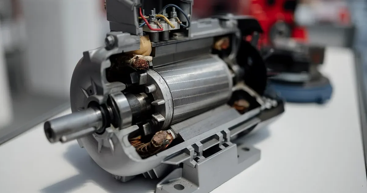
A servo motor exists to place a load accurately. The load moves because the shaft moves, and the shaft moves where the housing and bearings allow it. A flange that is out of square or a spigot that is off center shows up as a coupling that runs hot, a gearbox that wears early or an error in the position signal. That is why servo housings carry some of the tightest tolerances in motor machining.
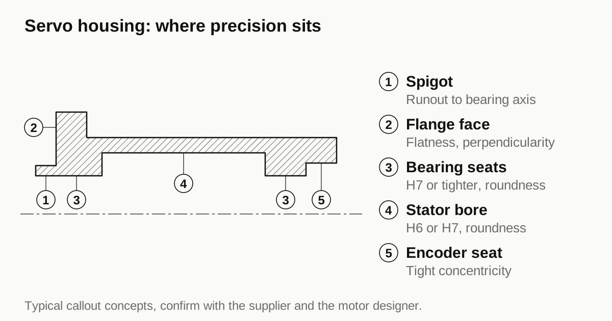
This guide explains where the precision sits on a servo housing, which tolerances are standard and what a shop needs to quote.
The parts of a servo housing
A servo motor has a compact, closed housing with several machined interfaces.
- Front flange. A square or round plate with mounting holes on a bolt circle. It bolts to the machine.
- Pilot or spigot. A short cylinder on the flange face that centers the motor in the machine’s bore.
- Front bearing seat. Holds the bearing nearest the output shaft.
- Shaft seal seat. For a lip seal, to keep oil and dust out. Many servo motors list an ingress protection rating.
- Stator bore. The central bore in which the stator is seated.
- Rear bearing seat and encoder end. The rear cover carries the second bearing and the position sensor.
- Cable or connector openings, usually with a sealed face and a thread.
Housings are mostly aluminum, machined from extrusion, bar or casting, with a steel or aluminum flange depending on the design. Small servo motors use a single piece housing and flange. Larger ones use a separate flange plate.
The alignment chain
Three relationships define alignment.
- Spigot to shaft axis. Concentricity or radial runout of the spigot against the bearing axis.
- Flange face to shaft axis. Perpendicularity, or axial runout, of the flange face against the bearing axis.
- Shaft runout. Radial runout of the shaft extension, which depends on the bearings and the shaft itself.
Standards such as IEC 60072-1 give normal and reduced tolerance classes for these items. The reduced class is tighter and costs more. Servo applications often call for the reduced class or an even tighter limit. The standard is the starting point, and the drawing has to state which class applies.
The bearing fit and runout guide explains why runout is the right callout for these relationships and why a vaguely drawn concentricity can cause confusion.
Typical fits and features
| Feature | Typical callout concept | Why |
|---|---|---|
| Spigot diameter | A fit class such as j6, with a tight runout to the bearing axis | Centers the motor in the machine bore |
| Flange face | Flatness and perpendicularity to the bearing axis | Prevents angular misalignment |
| Bolt holes | Position on a bolt circle with a clearance size | Allows mounting, not centering |
| Front bearing seat | H7 or tighter class with roundness | Holds the bearing without distortion |
| Stator bore | H6 or H7 with roundness | Shrink fit grip, as in the shrink fit guide |
| Encoder seat | Tight concentricity to the bearing axis | Keeps the position signal clean |
| Shaft seal seat | Bore with stated finish and chamfer | Seals without wear |
The classes shown are typical in motor design, and the actual values are set per design. The bearing seat fit reference lists bore limits for any diameter.
How shops hold the alignment
The spigot, flange face and bearing seats should be cut in the same clamping where possible. That gives coaxiality by construction, whatever the accuracy of the machine, and it is the main trick of precision servo housing work.
- Single setup machining. Turn the bearing seat, spigot and flange face on a lathe or turn mill in one chucking, or hold the part on a fixture that locates on the bearing seat for the second operation.
- Finish after stress relief. Rough, relax and finish, as in other thin walled housings.
- Gauge in process. Spigot and bore gauges at the machine reduce scrap.
- Measure on a CMM or a roundness machine for the runout and perpendicularity values, not with a hand gauge.
If the housing has to be flipped to machine the rear, the shop uses a ground or bored datum that survives the flip, and the quote reflects the extra inspection.
Heat, growth and servo accuracy
A servo motor runs hot in short bursts, and the housing grows as it warms. Aluminum expands about 23 micrometers per meter per kelvin, so a 100 mm long housing that warms by 40 K grows around 0.09 mm. For the bearing seats, which are fixed in relation to each other, the growth is mostly common to both. What matters is the difference between the housing and the shaft, since a steel shaft grows at about half that rate.
This difference changes bearing preload. Servo designs handle it with a spring preload or a floating rear bearing, so the housing drawing has to leave the rear bearing seat free to move axially in the way the designer planned. A shop that fits the rear seat too tightly in the axial direction can lock the bearing and cause a failure after the first warm up.
The same growth affects the encoder. The encoder disc sits on the shaft and the read head sits in the housing, so any growth between them changes the gap. Encoder makers publish a tolerance on that gap, and the housing’s encoder seat has to hold it across the working temperature range. If your motor works over a wide temperature range, state it on the RFQ so that the shop knows that dimensions are measured at 20 degrees C and the designer has allowed for the rest.
Need a quote for this part? Get a quote for your motor part
Seals and ingress protection
Many servo motors carry an IP65 or IP67 rating on the housing and shaft. The housing carries three seals.
- Shaft seal. A lip seal in a seat at the front bearing. The seat’s bore and finish, and the shaft’s surface under the lip, have to meet the seal maker’s data.
- Flange seal. An O-ring or flat gasket between the motor and the machine. The spigot diameter, the groove depth and the face finish matter.
- Connector and cable seals. A sealing face under the connector flange, and a thread or bayonet.
The dimensions come from the seal maker’s table. A groove cut a few hundredths too deep loses squeeze and leaks, and a groove cut too shallow crushes the seal. The shop needs the groove depth and width stated with a tolerance, not a general note.
Material choices
Servo housings mostly use aluminum, for thermal reasons and weight. A few notes on the common choices:
- Extruded 6063 or 6061 for square section housings, machined at the ends. Cheap per part and good for moderate volume.
- Cast aluminum for complex shapes with integrated features. Needs a plan for porosity if the housing has a cooling path or a sealing face.
- Machined from billet for prototypes and small runs.
- Steel flanges for heavier servo motors, where the flange carries high loads and aluminum would wear at the bolt faces.
The thermal conductivity guide explains why alloy choice affects cooling less than designers often expect.
Prototype and production
Servo makers often prototype with machined housings in the first run and move to a standard extruded or cast housing later. The drawing for the prototype should carry the same datums that the production housing will use, so that measurements carry over. A prototype housing machined in a different setup from the production plan has different error sources, and test results on it can mislead.
A useful habit is to ask the shop to report the actual measured values of spigot runout, flange perpendicularity and bore size on the first few parts, not just pass or fail. The numbers tell the designer how much margin exists, which a pass or fail result does not.
See also: servo motor housings and flanges by construction, with tolerance classes N and R and routes by volume.
What drives cost on a servo housing
- Tolerance class. Reduced class concentricity and perpendicularity need extra care, more checks and sometimes a finish operation.
- Number of setups. Each re-clamping adds an error chain and a cost.
- Material and blank. Extruded or cast blanks cost less than billet at volume. See the extrusion guide.
- Surface finish and coating. Anodize or paint on a visible housing, with masking at the fits.
- Inspection. CMM reports on each part cost time.
- Volume. A servo model sold in thousands justifies dedicated fixtures.
Questions to ask a shop
- How many setups does this housing need, and which features share one?
- What do you measure the spigot runout and flange perpendicularity with?
- Which datum survives the flip, if the part is turned over?
- Can you quote the reduced tolerance class and what it adds?
- How do you protect the machined spigot and flange face in shipping?
For the bearing seat, preload and gauging callouts behind a servo housing, read the guide to motor housing tolerances.
Checklist before you send the RFQ
- State the flange standard and size, or give the full dimensions.
- State the tolerance class for spigot concentricity, flange perpendicularity and shaft runout.
- Mark bearing seats with the bearing number and the fit.
- Mark the encoder seat and its tolerance.
- State material, finish and masking.
- State volume and whether the first parts are prototypes.
When the drawing is ready, send the RFQ and we quote the finished parts and place the work with a partner shop that machines servo and other motor housings. Replies come within 24 business hours.
Standards and references
- Servomotor, overview of servo motor construction and use. Background on the encoder and why alignment matters.
- IEC 60072-1, Dimensions and output series for rotating electrical machines. Standard flange, spigot and shaft dimensions and tolerance classes. Check the current edition.
- ISO 1101, Geometrical product specifications (GPS), Geometrical tolerancing. Runout, perpendicularity and position callouts used on flange drawings.
- ISO 286-1, ISO code system for tolerances on linear sizes. Fit classes for the spigot, shaft and bearing seats.
Figures on this page are typical ranges drawn from the standards above and from ordinary shop practice. They are not a specification for your part. The partner shop that prices your part confirms what it can hold on your geometry.
Frequently asked questions
Which tolerance matters most on a servo flange?
Concentricity of the spigot to the shaft axis, and perpendicularity of the flange face to that axis. Together they set how well the shaft aligns with the machine's coupling or gear. The flange outline and bolt holes matter far less than those two.
Do servo motors use the same flange dimensions everywhere?
Many use standard flange sizes with defined spigot diameters and bolt circles, so that motors from different makers swap. Some makers use their own series. The drawing should state the standard or the exact dimensions, since a close but different flange does not mount.
Why is the encoder end of the housing a separate concern?
The encoder or resolver reads rotor position, so its mounting must keep a fixed relation to the shaft. The housing end that carries it needs a seat with tight concentricity, or the position signal picks up an error once per turn.
Need a quote for this part?
Send the drawing. We quote the finished parts, place the work with a partner shop and reply within 24 business hours.
Get a quote for your motor part