Guides / Tolerances
IP67 Sealing Faces and Gasket Grooves on Motor Housings: What the Drawing Must Control
Written by the team that reads your RFQPublished How we write these
IP67 is a test result on a finished motor, but most of it is decided by features a machine shop cuts: the sealing face, the gasket or O-ring groove, the pilot and the bolt circle. A groove that is a few hundredths of a millimetre too deep leaves the seal loose. A face with tool marks across the groove leaks even when the Ra number is fine. This guide covers what IP67 requires, the groove numbers a drawing should carry and the checks that matter on a machined housing.
What IP67 requires
The IP code comes from IEC 60529. Each digit is a separate test. According to the IP Code overview:
- Digit 6, dust: dust-tight, no ingress of dust, tested with a vacuum applied for up to 8 hours depending on airflow.
- Digit 7, water: immersion with the enclosure’s lowest point 1,000 mm below the surface or its highest point 150 mm below, whichever is deeper, for 30 minutes, in fresh water.
Three consequences for a housing drawing. First, 1 m of water is a low pressure, about 9.8 kPa from rho times g times h. The seal does not need a high squeeze to resist it. It needs to be continuous, with no leak path. Second, the same page notes that ratings above IPX6 are not cumulative, so IP67 does not include the jet test of IP66. If the motor is washed down, the RFQ should say IP66 and IP67. Third, IPX8 is whatever the maker and buyer agree, so a buyer who needs deeper or longer immersion has to name the depth and time.
The code tests a complete motor with its shaft seal, cable gland, terminal box and cover joints. The housing is one source of leaks among several, but it is the one that is cut from metal and can be fixed on the drawing.
The face seal gland
Most flange and cover joints on motor housings use a face (axial) O-ring in a groove, or a flat gasket between two faces. For the O-ring case the groove is a standard gland. AS568 sizes and ISO 3601 housing dimensions are the references named for O-rings. For a face seal the seal supplier data give three numbers per cross-section: groove depth, groove width and corner radius.
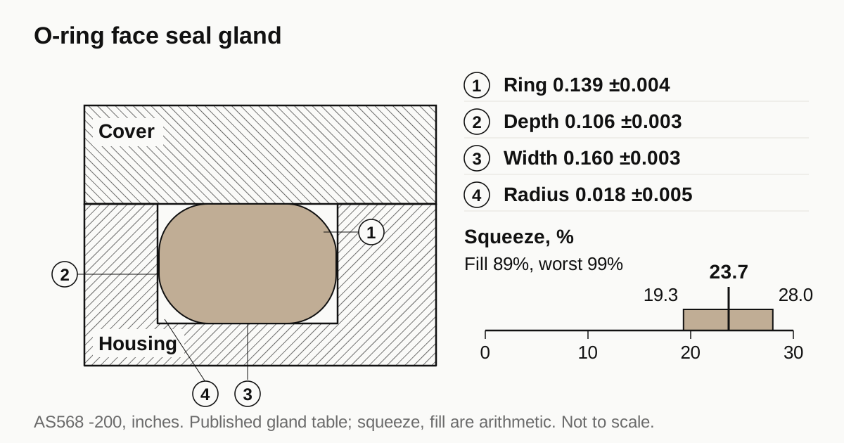
As an example, Marco Rubber lists these default values for an AS568 -200 series ring:
| Item | Value | Tolerance |
|---|---|---|
| O-ring cross-section | 0.139 in (3.53 mm) | ±0.004 in |
| Groove depth | 0.106 in (2.69 mm) | ±0.003 in |
| Groove width | 0.160 in (4.06 mm) | ±0.003 in |
| Groove corner radius | 0.018 in (0.46 mm) | ±0.005 in |
The supplier calls these default recommendations for basic applications, so they are a starting point and not a rule for every housing. The same page asks you to check them for your own fluid and pressure.
Squeeze and fill: the arithmetic
Squeeze is how much the ring is compressed between the groove bottom and the mating face, shown as a percentage of cross-section: (cross-section minus depth) divided by cross-section. With a cover that lands directly on the housing face, MN Rubber states the groove depth equals the recommended gland depth, so the groove depth is the squeeze dimension. Using the table above, my own arithmetic gives:
- Nominal squeeze: (0.139 minus 0.106) / 0.139 = 23.7 percent.
- Minimum squeeze: smallest ring (0.135) in the deepest groove (0.109) = 19.3 percent.
- Maximum squeeze: largest ring (0.143) in the shallowest groove (0.103) = 28.0 percent.
Squeeze moves by nearly 9 percentage points inside the tolerances before the flange has flexed at all. The groove depth tolerance, ±0.003 in or ±0.076 mm, is the part the machine shop controls, so it belongs on the drawing as a tolerance and not as a nominal.
Gland fill is the other check. The ring cross-section area, pi/4 times 0.139 squared, is 0.0152 square inches. The nominal groove area, 0.106 by 0.160, is 0.0170 square inches, so the fill is 89 percent. MN Rubber gives about 90 percent as a rule of thumb and says a fill above 100 percent means the groove has to be redesigned. At the worst corner of the tolerances, the largest ring in the smallest groove, the fill reaches about 99 percent before the corner radii are counted. The radii add volume, so the real figure is lower, but the margin is thin. Specify the groove width tolerance and the radius as well as the depth.
Two more points from the supplier pages. If the installed stretch of the ring exceeds about 3 percent, MN Rubber says to pick the next larger ring or request a custom one. And a groove design that works for oil with tight tolerances should be verified by test when the pressure, the tolerances or the fluid differ.
Surface finish and tool marks
Marco Rubber recommends 16 Ra maximum for gases and 32 Ra maximum for fluids, in microinches. That is roughly 0.4 and 0.8 micrometres. IP67 is a water test with air inside the housing, so the 32 Ra limit for the groove walls and the mating face is the sensible floor, and a gas-tight sealing face has the tighter figure. The page does not define the measurement direction, so put it on the drawing.
Roughness is not the whole story. The usual leak paths on a machined housing are:
- Tool marks that cross the groove. A face milled with a spiral lay can leave a scratch that runs from the inside of the groove to the outside, under the ring. Cut the groove last, or finish it with a lay that runs around the groove.
- Burrs at the groove edge and at the bolt holes. A burr on the sealing face lifts the cover locally.
- Porosity on the sealing face. A cast housing machined through the skin can open pores that run from inside to outside. The casting porosity guide covers impregnation and reject limits.
- Paint and coating on the sealing face. Anodize or e-coat build up on a face changes the squeeze. Mask the face or specify the coating thickness. The coating guide covers the options.
Need a quote for this part? Get a quote for your motor part
Flatness and bolt spacing
No public rule gives a flatness number for a motor flange, so the drawing has to carry its own value for the sealing face, using a flatness or profile callout under ISO 1101, and it should say whether the callout applies before or after coating. A bolted flange only presses the gasket evenly if the faces are flat and the bolts are close enough to the groove that the flange does not bow between them. Check this at the drawing stage with the motor designer, because the machine shop cannot fix a flange that is too thin once it is cut.
Pilots matter too. When the cover also locates on a spigot, the gearmotor adapter plate guide shows how the fit and runout of the pilot are written. A pilot that is off-centre pinches the ring on one side.
Vents and the thermal cycle
A sealed housing breathes as it heats and cools. Gore’s FAQ states that temperature changes create rapid pressure differences, and a vent equalizes them to reduce stress on the housing and the seals. Many vents are rated IP67 on submersion, 1 m for 30 minutes, with the rating given in the data sheet of each vent. The vent hole is a feature the machine shop cuts in the housing wall: a threaded or press-fit port, with its own sealing face. If the motor design includes one, the port needs the same controls as the cover joint: finish, burr removal and a stated thread class.
What goes on the RFQ
- The IP rating wanted, written as IP67 or IP66/IP67, and the water type if it is not fresh water.
- For each O-ring groove: the AS568 or ISO 3601 size, groove depth, width and corner radius, each with a tolerance.
- Surface finish on the groove walls and the mating face, with the lay direction.
- Flatness of the sealing face and whether it applies before or after coating.
- Masking of sealing faces during anodize or e-coat.
- Leak or pressure test requirement, and who runs it. The water jacket leak test guide covers pressure decay and helium methods.
- The motor drawing, the quantity and the delivery date.
For a quote, send the RFQ with the drawing. We quote the finished parts and place the work with a partner shop that machines motor housings, with a reply within 24 business hours. A seal that works on a CAD model has to survive a lathe, a coating line and a 30 minute immersion, and the shop that tells you how it will hold the groove depth is the one to talk to first.
Sources
- IP Code (IEC 60529), overview
- Marco Rubber, O-ring groove design, face seals
- MN Rubber, Groove design for O-ring seals
- Gore, FAQ on protective vents
- O-ring, overview
Standards and references
- IP Code (IEC 60529), overview. Meaning of the dust digit 6 and the water digit 7, the 30 minute immersion test, 1,000 mm depth rule and the point that ratings are not cumulative above IPX6.
- Marco Rubber, O-ring groove design, face seals. AS568 face seal gland width, depth and corner radius with tolerances, and the 16 Ra gas and 32 Ra fluid finish limits. Seal supplier document, default recommendations.
- MN Rubber, Groove design for O-ring seals. Face seal groove depth rule, clearance, the 90 percent gland fill rule of thumb and the 3 percent stretch limit. Seal supplier document.
- Gore, FAQ on protective vents. Why sealed enclosures need pressure equalization and how vents are rated. Vent maker document.
- O-ring, overview. AS568 and ISO 3601 size and housing standards for O-rings.
Figures on this page are typical ranges drawn from the standards above and from ordinary shop practice. They are not a specification for your part. The partner shop that prices your part confirms what it can hold on your geometry.
Frequently asked questions
What does IP67 mean for a motor housing?
The first digit 6 means dust-tight, with no dust ingress under vacuum test. The second digit 7 means the enclosure survives immersion for 30 minutes, with its lowest point 1,000 mm under the surface or its highest point 150 mm under, whichever is deeper. It says nothing about jets, steam or salt water.
Is an IP67 motor also rated IP66?
Not automatically. Ratings above IPX6 do not imply the lower water tests, so a housing that passes immersion is not certified for powerful jets unless it was also tested for them. A washdown motor is often written IP66/IP67 on the nameplate for that reason.
How smooth must an O-ring sealing face be?
One seal supplier gives 32 Ra microinch maximum for fluids and 16 Ra for gases, which is about 0.8 and 0.4 micrometres. Surface roughness alone is not enough: tool marks that cross the groove, burrs and scratches leak even when Ra passes. Ask for the lay as well as the number.
Does an IP67 motor need a breather vent?
Often, yes, when the motor heats and cools. A fully sealed housing draws a vacuum as it cools and pulls on the seals. Vent makers sell membrane vents rated up to IP67 for this. Whether a given motor needs one is a design decision for the motor maker, so state it on the RFQ.
Need a quote for this part?
Send the drawing. We quote the finished parts, place the work with a partner shop and reply within 24 business hours.
Get a quote for your motor part