Guides / Tolerances
Gearmotor Adapter Plates and Flanges: Pilot Fits, Runout and What the Drawing Must Say
Written by the team that reads your RFQPublished How we write these
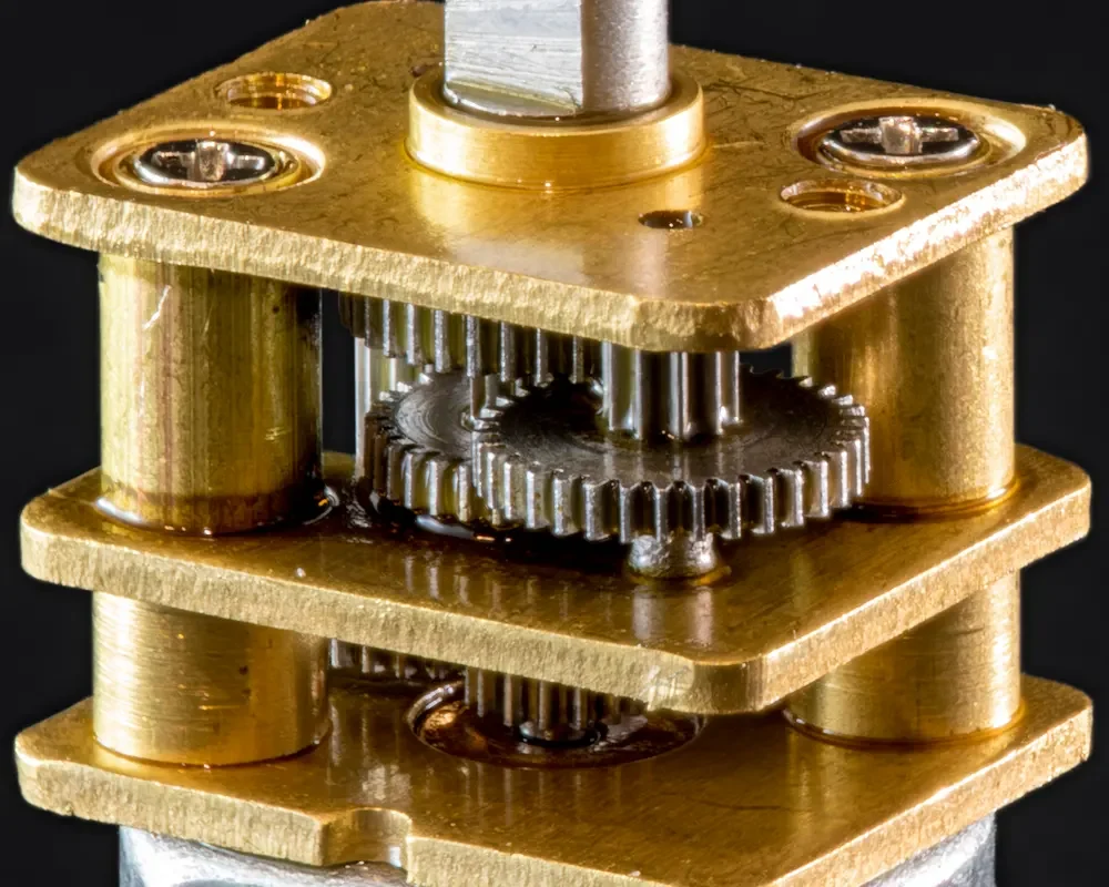
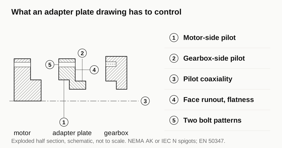
A gearmotor adapter plate sits between a motor and a gearbox, or between a motor and a pump, when the two do not share a flange standard. It has two pilots and two bolt patterns, one pair per side, and its job is to make the motor shaft and the gearbox input shaft run on one axis. Four things decide whether it does that: the diameter and fit of each pilot, how well the two pilots share an axis, how square the two faces are to that axis and whether the bolt patterns match the parts they join.
Know both standards before drawing the plate
NEMA names the motor side of a C-face mount with three letters: AJ for the bolt circle, AK for the rabbet or pilot diameter and BD for the flange outside diameter. The ABB (Baldor-Reliance) quick reference chart gives these values:
| NEMA frame | AJ bolt circle | AK pilot | BD flange | Tapped holes in the chart |
|---|---|---|---|---|
| 56 and 143T | 5-7/8 in (149.2 mm) | 4-1/2 in (114.3 mm) | 6-1/2 in (165.1 mm) | 3/8-16 |
| 182T | 7-1/4 in (184.2 mm) | 8-1/2 in (215.9 mm) | 9 in (228.6 mm) | 1/2-13 |
The millimetre figures are conversions. The chart marks the N, O, P, AB and XO dimensions as specific to Baldor-Reliance and the AJ, AK and BD values are not on that list, but confirm them against the drawing of the actual motor.
The IEC side uses M for the pitch circle, N for the spigot, P for the outside diameter, S for the hole and T for the flange thickness. The ABB IEC chart gives these values, in millimetres:
| IEC frame | B5 flange M / N / P | B5 holes S | B14 face M / N / P | B14 threads |
|---|---|---|---|---|
| 63 | 115 / 95 / 120 | 7 | 75 / 60 / 90 | M5 |
| 71 | 130 / 110 / 160 | 10 | 85 / 70 / 105 | M6 |
| 80 | 165 / 130 / 200 | 12 | 100 / 80 / 120 | M6 |
| 90 | 165 / 130 / 200 | 12 | 115 / 95 / 140 | M8 |
| 100 and 112 | 215 / 180 / 250 | 15 | 130 / 110 / 160 | M8 |
| 132 | 265 / 230 / 300 | 15 | 165 / 130 / 200 | M10 |
Two traps show up in the table. Frame 71 B5 and frames 100 and 112 B14 share the same pitch circle, spigot and outside diameter, at 130, 110 and 160 mm. Frame 80 B5 and frame 132 B14 do the same at 165, 130 and 200 mm. The difference is the hole: a B5 flange has clearance holes and a B14 face has threaded ones. An adapter plate drawn from the diameters alone can look right and still be wrong for the motor in hand.
The NEMA publication on mounting types lists C-face, D-flange, IEC B5 and IEC B14 and names NEMA MG 1 and IEC 60034 as the two governing standards. Which one applies to the gearbox side is a separate question from the motor side, so the plate often carries one standard on each face.
The pilots: diameter and fit
The pilot is the male or female register that centers the part. Two numbers matter: its diameter and its fit class.
SEW, citing EN 50347, lists the IEC flange centering shoulder as ISO j6 for diameters up to 250 mm and ISO h6 from 300 mm. The page does not give a class between 250 and 300 mm. NEMA publishes the rabbet tolerance too. Nidec’s table for Type P motors (clause MG 1-18.590) gives an AK tolerance of +0.003 in and minus 0.000 for frames 182 to 286, and +0.005 in and minus 0.000 for frames 324 to 445. Those figures are for vertical P-base motors and not for ordinary C-face flanges, so they show how NEMA writes the tolerance and not the value for your motor. Take the real limit from the motor maker’s drawing.
The plate bore that receives a motor spigot is the designer’s choice. Wikipedia’s page on engineering fits defines a location fit such as H7/h6 as assembled without force, and a transition fit such as H7/k6 as assembled with a rubber mallet. A tighter fit centers better and costs more to hold, and it makes assembly harder when the motor is swapped in the field. The bearing fit reference lists bore limits for any diameter, so the drawing can state limits and not only a class.
Coaxiality of the two pilots
The plate’s most important feature is not on either pilot alone. It is the relation between them. If the motor-side bore and the gearbox-side spigot are not on one axis, the two shafts run offset by that amount plus the play in both fits. Everything downstream, from coupling wear to seal life to bearing load, rises with that offset.
An illustrative sum, not a standard: suppose the drawing holds the two pilots coaxial within a 0.05 mm diameter zone, which is at most 0.025 mm of radial offset. Add a diametral clearance of 0.03 mm in each fit, which lets each pilot sit 0.015 mm off center. The worst-case offset between the two shafts’ axes is 0.025 + 0.015 + 0.015 = 0.055 mm, before the motor’s own spigot-to-shaft error. If the coupling or gearbox maker allows less than that, the plate drawing has to tighten the coaxiality or the fits. The coaxiality callout guide shows how to draw the datum.
The simplest way for a shop to hold coaxiality is to cut both pilots and both faces in one clamping. When the plate has to be flipped, the shop needs a datum that survives the flip, such as a bore cut in the first operation. Ask which method the quote assumes.
Need a quote for this part? Get a quote for your motor part
Face runout and flatness
The faces of the plate set the angle between the two shafts. Nidec’s page lists a face runout of 0.004 in (0.10 mm) for frames 182 to 286 and 0.007 in (0.18 mm) for frames 324 to 445, again for Type P motors. It lists a permissible shaft runout of 0.002 in (0.05 mm). Its note that the runout of the mounting rabbet is always twice the eccentricity matters when the drawing and the inspection report use different words: a rabbet runout of 0.05 mm equals an eccentricity of 0.025 mm.
The plate itself needs two things the motor drawings do not give. Its thickness sets how far the shaft reaches into the gearbox input, so the thickness tolerance is an axial position tolerance. And the two faces must be parallel, or the plate tilts one shaft against the other. For the measurement itself, Nidec describes an indicator on the shaft extension, rotated through 360 degrees, with the difference between the maximum and minimum readings as the result. A shop measuring a loose plate will use a CMM or a bore datum instead, so the drawing should state the datum the runout refers to. The servo flange guide covers the same alignment chain for a motor housing.
See also: the NEMA motor frame dimensions chart gives D, 2E, 2F, BA, U and N-W from frame 48 to 445T.
Bolt patterns and threads
Each side needs its own pattern. On NEMA C-face motors the motor face is tapped (3/8-16 for the 56 and 143T frames on the ABB chart), so the plate carries clearance holes on that side and the bolts come from the plate side. An IEC B5 motor uses clearance holes in its flange, so the plate side needs threaded holes or through holes with nuts. A B14 face is threaded. State on the drawing which side takes studs, bolts or screws, and the thread class of every tapped hole.
Tapped holes in an aluminum plate may need inserts if the plate is taken apart often. See the thread inserts guide. Hole position tolerances belong on the drawing as a position callout to the pilot datum, since a bolt circle that is off center fights the pilot.
What the drawing must say
| Feature | State on the drawing | Why |
|---|---|---|
| Motor-side pilot | Diameter, fit class, depth | Centers the motor |
| Gearbox-side pilot | Diameter, fit class, depth | Centers the gearbox |
| Pilot-to-pilot coaxiality | Tolerance and the datum | Sets shaft offset |
| Face runout and parallelism | Tolerance to the pilot axis | Sets shaft angle |
| Plate thickness | Tolerance | Sets axial position of the shaft |
| Bolt patterns | Pitch circle, hole size or thread, position tolerance | Fits both parts |
| Material and finish | Alloy, coating, masked areas | Corrosion and fit surfaces |
| Inspection | Report type and what is measured | Proves the above |
The motor housing side of the same alignment chain is in our guide to motor housing tolerances.
Questions to ask a shop
- Are both pilots and both faces cut in one setup, or is the plate flipped?
- What do you measure coaxiality and face runout with?
- Can you supply a measurement report for the first plates, with values and not only pass or fail?
- Do you hold the fit class on both pilots or only the diameter?
- How do you protect the pilots and faces in shipping?
No public price survey exists for adapter plates, so compare quotes on the same drawing with the same tolerances. The processes page explains the turning and boring operations behind a plate like this.
When the drawing is ready, send the RFQ and we quote the finished parts and place the work with a partner shop that machines motor flanges and housings, with a reply within 24 business hours.
Standards and references
- SEW-EURODRIVE, installation tolerances for motor shaft ends and flanges. EN 50347 tolerance classes: flange centering shoulder ISO j6 up to 250 mm and ISO h6 from 300 mm, plus the shaft end classes. Manufacturer document.
- Nidec Motor, Measuring shaft runout (NEMA tolerances for Type P motors, MG 1-18.590). Rabbet diameter tolerance, face runout and shaft runout by frame range, the rule that rabbet runout is twice the eccentricity, and how the readings are taken. Manufacturer document.
- ABB (Baldor-Reliance), NEMA quick reference chart. AJ, AK and BD for the 56, 143T and 182T frames and the tapped hole size column.
- ABB (Baldor-Reliance), IEC frame dimension chart for B5 flange and B14 face mounting. Pitch circle M, spigot N, outside diameter P, hole size S and flange thickness T for frames 63 to 132.
- Engineering fit, ISO fit classes. Definitions of clearance, transition and interference fits and the H7/h6 location fit.
- NEMA, Motor mounting types. C-face, D-flange, IEC B5 and B14 mounting types, with NEMA MG 1 and IEC 60034 named as the two global standards.
Figures on this page are typical ranges drawn from the standards above and from ordinary shop practice. They are not a specification for your part. The partner shop that prices your part confirms what it can hold on your geometry.
Frequently asked questions
What do AJ, AK and BD mean on a NEMA C-face motor?
AJ is the bolt circle, AK is the rabbet or pilot diameter and BD is the flange outside diameter. On the ABB chart the 56 and 143T frames list AJ 5-7/8 in, AK 4-1/2 in and BD 6-1/2 in. The 182T frame lists AJ 7-1/4 in, AK 8-1/2 in and BD 9 in.
Can one adapter plate fit a B5 and a B14 motor?
Only if it carries both hole types. B5 flanges use clearance holes and B14 faces use threaded holes. Some frames share the same pitch circle, spigot and outside diameter, for example frame 80 B5 and frame 132 B14 at 165, 130 and 200 mm, so the hole type is the difference to check.
What tolerance does the motor spigot have?
SEW, citing EN 50347, lists the flange centering shoulder as ISO j6 for diameters up to 250 mm and ISO h6 from 300 mm. The page is silent between 250 and 300 mm. The plate bore is then set by the fit the designer wants, such as a location or transition fit.
How is flange runout measured?
Nidec describes mounting an indicator on the shaft extension, with the eccentricity indicator at about the middle of the rabbet and the face runout indicator at about the outer diameter of the mounting face. The shaft is rotated through 360 degrees and the reading is the difference between the maximum and the minimum.
Need a quote for this part?
Send the drawing. We quote the finished parts, place the work with a partner shop and reply within 24 business hours.
Get a quote for your motor part