Guides / Tolerances
Shaft Grounding Rings and Insulated Bearings: What the Motor Housing Drawing Has to Provide
Written by the team that reads your RFQPublished How we write these
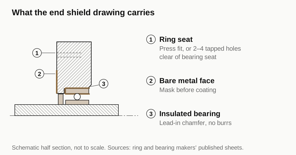
A grounding ring or an insulated bearing adds three things to an end shield drawing: a seat for the ring or a set of tapped holes, a bare metal path from the ring to the frame, and a lead-in chamfer where an insulated bearing goes in. The motor designer chooses the protection. The drawing then has to carry the matching features, and a shop that is not told about them will machine, coat and ship an end shield that cannot take the ring.
Why the end shield is involved
Wikipedia’s drive article says PWM drives are inherently associated with high-frequency common-mode voltages and currents, and that carrier frequencies above 5 kHz are likely to cause bearing damage unless protective measures are taken. The mechanism is described on the VFDs.com page: voltage builds across the bearing until it exceeds the breakdown level of the oil film, then arcs through it. Each arc leaves an EDM pit, and over time the rolling elements run over the disturbed surface and form a fluting pattern.
SKF puts a number on the risk: it arises when transient voltages exceed 0.5 V or the current is more than 0.1 A per square millimeter of rolling contact area. Neither figure is something a machine shop controls. They explain why the motor designer adds protection, and why the protection shows up on the housing.
Two remedies, two sets of housing features
| Insulated bearing | Shaft grounding ring | |
|---|---|---|
| What it does | Blocks the current path through the bearing | Gives the shaft current a route to the frame that avoids the bearing |
| Where it sits | Outer ring coating or ceramic parts inside the bearing seat | On the shaft, at the end shield |
| Housing feature | Standard bearing bore, with a lead-in chamfer | Press-fit seat, or tapped holes, or bolt-through holes |
| Effect on shaft voltage | Voltage remains, the path through the bearing is blocked | The current is diverted to the frame |
The VFDs.com page describes insulated bearings as using ceramic balls or an insulating ring between bearing and frame. SKF’s coated version uses an aluminum oxide layer plasma sprayed on the outer ring, about 0.05 mm thick, rated at either 500 V or 1,000 V depending on the suffix. In asymmetrical motors SKF says typically only the smaller non-drive-side bearing needs insulation. Which end carries the protection is the designer’s decision, and it should be on the drawing for each end shield.
Drive systems use other remedies as well. The Wikipedia list includes cabling and grounding practice, filters and common-mode chokes, and shielded motors. Those sit outside the housing and are not covered here.
What a ring asks of the end shield
The AEGIS installation sheet (vendor data, so directional only) lists three mounting styles. Each puts something different on the drawing.
Press fit. The ring is pressed into a bore in the end shield. The sheet specifies a clean dry press fit, with no oil or lubricant. One catalog size, for shafts of 67.3 to 68.2 mm, gives a ring diameter of 90.932 mm +0/-0.025 and a bore of 90.830 mm +0.025/-0 with a fit of 0.051 to 0.102 mm. The bore tolerance band is 25 micrometers. ISO 286 gives 22 micrometers for IT6 and 35 for IT7 in the 80 to 120 mm range, so the seat sits between the two grades. This is one size from one vendor, and the numbers change with shaft size, so copy the ring maker’s drawing for your shaft and do not reuse them.
Clamp-on. Small brackets hold the ring against the end shield. The shield needs 2 to 4 tapped holes. For the metric hardware the sheet gives a 2.5 mm drill, 6 mm depth and an M3 tap, and it says not to drill into the bearing. That is a position problem on the drawing: the holes must sit clear of the bearing seat and any pocket behind it.
Bolt-through. The ring is secured with screws that go into tapped holes in the end bell, to a depth of about 6 mm. The sheet does not give a hole count.
Two shaft conditions come from the same sheet. The contact area on the shaft has to be free of keyways and balancing holes, clean to bare metal, with a basic surface resistance under 2 ohms. A shoulder or slinger shorter than 9.5 mm calls for a different ring style. These items belong on the rotor drawing, so the shaft shop and the housing shop need the same revision of the design.
Need a quote for this part? Get a quote for your motor part
Coatings that cut the path
The installation sheet asks for a ring-to-frame reading under 1 ohm after fitting and says not to use Loctite or any other non-conductive material. It follows that a coating that insulates, such as e-coat or powder coat, must not cover the seat, the clamp pads or the screw bosses. SKF’s own insulation is aluminum oxide, which hints at the same trap on aluminum shields: an anodized face is a poor electrical contact. This reading is an inference from the vendor sheet, not a rule quoted from a standard, so confirm it with the ring maker. The practical step is clear either way. Put the masking on the drawing as a note with a view of the area. The guide on anodize, e-coat and powder coat lists how shops mask.
What an insulated bearing asks of the bore
SKF says the coated bearings follow ISO standard dimensions and tolerances and are interchangeable with non-insulated types. So the bore does not change. Two details do. SKF advises a 15 degree chamfer on the housing bore on the side where mounting starts, to ease fitting in tight housing fits. The coating is hard but not unbreakable, so burrs and sharp edges at the bore mouth should be removed. Alignment still comes from the housing, as in the guide to bearing bore coaxiality, and the size limits are in the bearing fit reference.
Drawing checklist
- Which end shield carries the protection and which type: ring or insulated bearing.
- Ring style and a copy of the ring maker’s drawing for the shaft size.
- Seat bore or tapped holes, with positions relative to the bearing seat and a note not to drill into the bearing.
- Masked areas that must stay bare metal, shown in a view.
- Lead-in chamfer on the bearing bore if the bearing is insulated.
- A continuity check between the ring seat and the frame, with the target resistance the designer wants.
- Shaft contact area, free of keyways and balancing holes, on the rotor drawing.
The other end shield and bearing seat callouts are collected in the motor housing tolerances guide.
NEMA MG1 Part 31 and IEC TS 60034-25 deal with inverter-fed machines. This guide does not quote their thresholds because the standards are not public and only secondary summaries were available. Read the current text before you set a requirement.
When the end shield drawing is ready, send the RFQ and we quote the finished parts and place the work with a partner shop that machines motor parts, with a reply within 24 business hours. The page on how partner shops are chosen explains the checks.
Standards and references
- Variable-frequency drive, section on motor bearing currents. High-frequency common-mode voltage from PWM drives, the 5 kHz carrier remark, EDM fluting and the list of remedies.
- SKF, Electrically insulated bearings (INSOCOAT). Damage thresholds, aluminum oxide coating on the outer ring, 500 V and 1,000 V ratings, ISO dimensions and the housing chamfer advice.
- AEGIS shaft grounding ring, installation instructions (vendor). Press fit, clamp-on and bolt-through mounting, tapped hole sizes, shaft and resistance requirements. Vendor data, directional only.
- AEGIS SGR catalog page for shafts of 67.3 to 68.2 mm (vendor). One worked press-fit size with ring diameter, bore diameter and fit. Vendor data for one size only.
- VFDs.com, Bearing currents (vendor). How voltage breaks down the oil film, EDM pits and fluting, insulated bearings versus a ring. Vendor page.
- IT Grade, table of ISO 286 tolerance grades. IT6 and IT7 widths for the 80 to 120 mm range, used to size the ring seat tolerance.
Figures on this page are typical ranges drawn from the standards above and from ordinary shop practice. They are not a specification for your part. The partner shop that prices your part confirms what it can hold on your geometry.
Frequently asked questions
Why do VFD-driven motors need a grounding ring or insulated bearings?
PWM drives produce high-frequency common-mode voltage. According to Wikipedia, carrier frequencies above 5 kHz are likely to cause bearing damage unless protective measures are taken. The voltage arcs through the bearing oil film and leaves EDM pits that turn into fluting over time.
Does an insulated bearing stop shaft voltage?
No. It blocks the current path through that bearing, but the shaft voltage remains. A grounding ring gives that current another route to the frame instead. The motor designer picks one or both, and the housing drawing then has to carry the matching features.
Does a grounding ring need a special bore in the end shield?
Only the press-fit style does. It sits in a bore in the bearing end cap. Clamp-on and bolt-through rings need two to four small tapped holes in the end bell. Get the ring maker's drawing for your shaft size, because dimensions are not standard across frames.
Can the end shield be anodized or painted where the ring fits?
Not where the ring must make electrical contact. The installation sheet asks for a ring-to-frame reading under 1 ohm and says not to use non-conductive material. Mask the seat or the clamp pads so the metal stays bare, and say so on the drawing.
Need a quote for this part?
Send the drawing. We quote the finished parts, place the work with a partner shop and reply within 24 business hours.
Get a quote for your motor part