Guides / Buyer Guide
E-Bike Hub Motor Shells and Side Covers: What to Specify for Machining
Written by the team that reads your RFQPublished How we write these
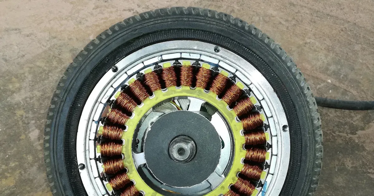
A hub motor sits in the middle of a wheel. The outer shell carries magnets and spins, the stator sits fixed on the axle inside, and two side covers close the shell and hold the bearings. Spokes or a disc rim attach to flanges on the shell, and the whole assembly has to run true on a bike or scooter that rides on it daily. That makes the shell and the covers precision parts, even though they look simple.
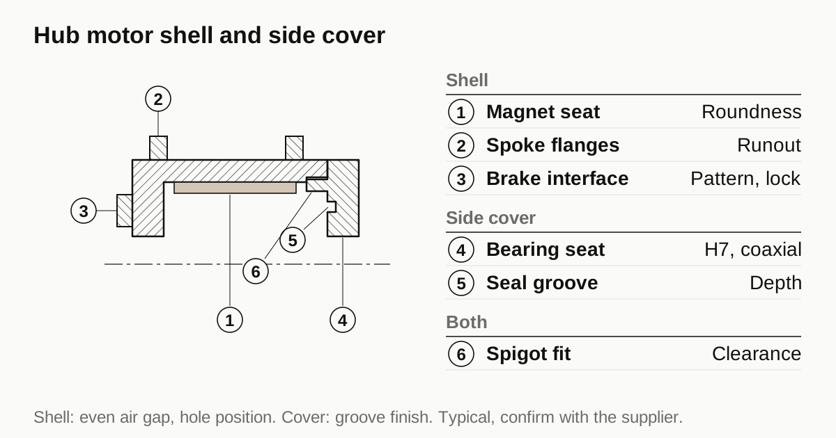
This guide lists the features of each part, the fits and tolerances that matter and the details a machine shop needs on the RFQ.
Anatomy of a hub motor
A typical hub motor has these machined parts.
- Shell, also called the hub or casing. A round body with a magnet seat on the inside and spoke flanges on the outside.
- Left and right side covers. Round plates that close the ends of the shell and carry the bearings.
- Axle, fixed to the stator and to the frame. It is machined with flats, threads and a cable slot.
- Stator, wound core fixed on the axle.
- Gear parts, in geared hub motors: a sun gear, planet carrier and a clutch, which are separate parts with their own specs.
- Optional parts: a freewheel body for a cassette, a disc brake flange and a cable gland.
Direct drive motors have no gear parts and a heavier shell. Geared motors have a smaller motor and a gear train inside the shell.
The shell
The shell is a large revolved part with several functions.
- Magnet seat. The inner surface carries the magnets, often bonded to a steel ring that is pressed into an aluminum shell, or glued directly to a steel shell. The seat has to be round and the right size, since the magnet to stator air gap depends on it.
- Spoke flanges. Two flanges carry the spoke holes, usually 32 or 36 holes per flange. Hole position and flange runout decide whether a wheel can be built straight.
- Brake interface. A disc brake mount, either six bolt or center lock, or a drum interface, sits on one side.
- Bearing seats or spigots. The side covers locate on the shell through a spigot fit.
- Cable path. A slot or hole on one side for the phase and sensor wires.
Shell materials are mostly aluminum alloys, such as 6061 or a cast alloy, with steel used for the magnet ring. For direct drive shells, the weight of aluminum helps. For tough scooter duty, forged or heavy cast shells are common.
The side covers
A side cover closes the shell and holds the bearing for the axle. Key features are:
- Bearing seat. Sized for the bearing, typically a standard deep groove ball bearing of the 6000 or 6200 series, with a tolerance in the H7 range for the bore.
- Axle clearance bore. Allows the axle to pass without touching.
- Spigot. Locates the cover on the shell. The spigot to bearing seat coaxiality decides how well the rotor stays centered.
- Seal groove or lip seat. Keeps water and dust out. A groove face with a poor finish leaks, and the surface finish needs a callout.
- Fastener holes, often 6 to 12 small screws, positioned on a bolt circle.
- Cable gland, where wires exit.
The cover is thin walled and flat, so it can distort when clamped. A shop that holds it on a vacuum chuck or with soft jaws and a light finishing pass avoids oval seats. The thin-wall guide describes the same issue on housings.
Key dimensions that come from the bike
The housing drawing is bound by external standards, not by the shop.
| Item | What it is set by | Typical values to check |
|---|---|---|
| Over locknut width | Frame or fork dropout | Rear 135, 142 or 148 mm; front 100 or 110 mm |
| Axle size and flats | Dropout design | 12, 14 or 15 mm axles; flat width on the axle |
| Spoke count and flange diameter | Rim and spoke choice | 32 or 36 holes, flange diameter by design |
| Disc mount | Brake standard | Six bolt or center lock |
| Rotor to stator air gap | Motor design | Set by the designer, held through shell bore and cover seats |
These values are typical for orientation. The frame, fork and brake makers publish the exact standards, so confirm them before releasing a drawing.
Fits and tolerances
Bearing seats. The housing bore for the bearing outer ring is usually H7 for steady loads. The bearing seat fit reference lists limits by diameter.
Spigot fit. The shell and cover spigot should fit with a small clearance so that the cover seats easily but cannot shift. Clearances in the range of a few hundredths of a millimeter are common.
Runout. Total runout of the spoke flange against the bearing axis keeps the wheel true. Values of a few tenths of a millimeter are usual for bike wheels, and a tighter value suits high speed scooters.
Roundness of the magnet seat. A round seat keeps the air gap even around the circumference, which reduces noise and cogging.
Surface finish. Seal lips and O-ring grooves need a stated roughness. Threads need clean, burr free cutting.
Direct drive and geared shells compared
The two hub motor layouts change what the shell has to do.
Direct drive. The magnets are on the shell and the shell turns at wheel speed. The motor is large in diameter and relatively heavy. The shell needs a strong magnet seat, since the magnets are bonded to a ring that carries large torque directly, and the air gap is tight and sensitive to roundness. There is no gear train, so the side covers only carry bearings.
Geared hub. A smaller, faster motor sits inside, and a planetary gear reduces the speed to the wheel. The shell carries the ring gear or the output carrier, and the side covers may hold gear bearings as well as the main bearings. The gear parts have their own accuracy needs, and the shell has to keep the gear axis aligned. In geared hubs the shell often has a clutch pocket or a freewheel interface, adding features that need careful machining.
For a buyer, the practical difference is the number of critical features. A geared shell has more of them, so the quote is higher and the first article inspection takes longer. Make clear on the RFQ which layout applies.
Need a quote for this part? Get a quote for your motor part
Magnet seat and the air gap
The magnets in a direct drive hub motor sit a fraction of a millimeter from the stator teeth. If the shell’s magnet seat is out of round or off axis, the air gap changes around the turn. A small gap on one side pulls the rotor toward the stator with a force that rises as the gap shrinks, which causes noise and uneven wear.
Shops control this by cutting the magnet seat and the bearing spigots in the same setup, so that they share an axis. If the shell has to be flipped to machine the second side, the shop uses a datum that survives the flip, such as a ground spigot or a bored seat. Ask how the shell is located for the second operation.
The depth and width of the magnet seat also matter. If magnets are glued, the seat needs a surface that takes adhesive, and any anodize or oil on it can stop the bond. Say whether the seat is to be left bare, cleaned or abraded, and whether the magnets are installed by the buyer or the shop.
Balance and wheel run
A hub motor is part of a wheel. An unbalanced shell makes the wheel vibrate at speed, and a shell with flange runout makes the rim wobble. Both are felt by the rider.
- Balance. The shell is usually balanced after the stator and magnets are installed. Machine shops help by keeping wall thickness even and mass symmetrical. The balancing guide explains how grades work and why they depend on speed.
- Flange runout. The spoke flange faces should run true to the bearing axis, so the wheel can be built without large spoke tension differences.
- Spoke hole quality. A burr or a sharp edge on a spoke hole cuts spokes over time. Edges are chamfered or countersunk to the spoke head seat.
Typical RFQ mistakes
| Mistake | Effect | Better |
|---|---|---|
| No bearing number on the drawing | Shop guesses the seat size | State the bearing type and the fit |
| Dropout width left out | Shop cannot check the part against the frame | Give over locknut width |
| No finish note on seal grooves | Leaks in service | State roughness |
| Coating not masked | Fit changes | Mark masked surfaces |
| Prototype quantity not stated | Quote assumes production fixtures | Say how many and when |
How the part is made
- Shell: turned from tube or billet, or from a cast or forged blank. The inner seat, spigots and flange faces are cut in one or two setups. Spoke holes are drilled on a rotary table or a drilling fixture. Disc mounts are milled.
- Side cover: turned from bar or plate or from a casting. Bearing seat, spigot and seal groove are cut together to keep them coaxial. Fastener holes and cable features follow.
- Finishing: anodize, powder coat or paint, with masking on bearing seats and spigots. The guide to coatings compares the options.
Checklist before you send the RFQ
- State over locknut width, axle size and flat details.
- Give spoke count, flange size and disc mount type.
- Mark bearing seats with the bearing number and fit class.
- Mark the spigot fit and the seal groove with finish.
- State runout limits and what they are measured against.
- State material, finish and masking.
- Give the quantity and whether prototypes come first.
When the drawing is ready, send the RFQ and we quote the finished parts and place the work with a partner shop that machines motor parts. Replies come within 24 business hours.
Standards and references
- Hub motor, overview of in-wheel motors and their layouts. Direct drive and geared hub layouts and where the housing parts sit.
- Brushless DC electric motor, overview. Background on the outer rotor design most hub motors use.
- ISO 286-1, ISO code system for tolerances on linear sizes. Bore classes for bearing seats and the magnet bore.
- ISO 4210, Cycles, Safety requirements for bicycles. The safety standard family that wheel and frame parts are assessed against. Check the current parts for electrically assisted cycles.
Figures on this page are typical ranges drawn from the standards above and from ordinary shop practice. They are not a specification for your part. The partner shop that prices your part confirms what it can hold on your geometry.
Frequently asked questions
What are the critical features on a hub motor side cover?
The bearing seat, its coaxiality with the axle bore and with the shell spigot, the seal groove and the face that sits against the shell. If the cover seats badly, the bearing runs hot and the seal leaks, so these features carry the tight tolerances.
Is the shell machined from billet, tube or a casting?
All three exist. Low volume shells are turned from tube or billet. Mid volume shells use a casting or forging as the blank. Which one fits depends on the shell size, the spoke flange design and the order quantity.
Do I need to fix the dropout width and axle size on the drawing?
Yes. Those come from the frame and fork standard, not from the machine shop. The housing drawing has to match them, so state the over locknut dimension, axle size and flat or thread details.
Need a quote for this part?
Send the drawing. We quote the finished parts, place the work with a partner shop and reply within 24 business hours.
Get a quote for your motor part