Guides / Tolerances
Bearing Bore Coaxiality in Motor Housings: Which GD&T Callout to Put on the Drawing
Written by the team that reads your RFQPublished How we write these
Two bearing bores in a motor housing have to share one axis, and the diameter tolerance on each bore does not guarantee it. Put a numeric alignment callout on the drawing: coaxiality if the drawing follows ISO 1101, or position or total runout if it follows ASME Y14.5. Tie both bores to a common datum axis and state the zone as a diameter. The rest of this guide explains how to choose and how to read what you wrote.
What the three callouts control
| Callout | Zone | What it limits | How it is checked |
|---|---|---|---|
| Coaxiality (ISO 1101) | Cylinder around the datum axis | Position of the feature axis relative to the datum axis | Digital measurement on a CMM or with optical sensors |
| Position (ASME Y14.5) | Cylinder around the true position, tied to datums | Location and orientation of the feature axis | CMM against the datum reference frame |
| Total runout | Whole surface, measured while the part rotates | Alignment together with form of the surface | Indicator or probe on a rotating part |
KEYENCE describes coaxiality as controlling the central axes of two cylinders, and concentricity as controlling center points. Total run-out is the run-out of the entire surface when the target is rotated, and circular run-out covers any single circumference. GD&T Basics notes that under ISO one symbol serves coaxiality and concentricity, and that ASME Y14.5 interprets concentricity and coaxiality very differently. Wikipedia adds that the 2018 ASME revision eliminated concentricity and symmetry. In practice ASME drawings use position or runout where ISO drawings use coaxiality, so first check which standard the drawing cites.
Coaxiality is one of five callout groups on a housing; the others are laid out in the motor housing tolerances guide.
Reading the zone
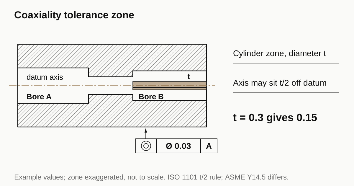
Coaxiality is a location tolerance and its zone is a cylinder. ZEISS gives the example of a 0.3 mm cylinder coaxial with the reference axis. The toleranced axis must lie inside it, so it is out of tolerance once it is more than 0.15 mm from the reference axis. The value is a diameter and the allowed offset is half of it.
A worked comparison shows why the size class does not do this job. Take a 52 mm bearing bore, which falls in the 50 to 80 mm size range. ISO 286 gives an IT6 width of 19 micrometers and an IT7 width of 30. An H7 bore is therefore allowed to vary in diameter by 0.030 mm. That says nothing about where the axis is. A bore with perfect diameter can sit 0.05 mm off the datum axis and still pass its size check. With a coaxiality zone of 0.03 mm, the same bore would fail. The two callouts control different things and a drawing needs both. The bearing fit reference lists the size limits and the guide on bearing fits, concentricity and runout covers the fit side.
The number itself is a design decision. This article does not give a standard ratio between the size tolerance and the alignment tolerance, because none is published for motor housings. Ask the motor designer or the bearing supplier for the target, then write it on the drawing.
Choosing the datum
The callout is only as good as the datum it refers to. Three arrangements are common on motor housings.
- One bore as datum A, the other bore coaxial to A. Simple to measure. Pick the bore whose alignment matters most as the datum, often the one next to the rotor or the one that takes the axial load.
- Both bores form a common datum axis A-B, and other features refer to A-B. This suits housings where the stator bore, flange pilot and end bell spigot must follow the bearing axis, not one bearing alone.
- Separate housing and end bell. The bores sit in two parts, so alignment comes from the spigot fits between them. Control the spigot to bore alignment on each part. A tolerance on the assembled stack cannot be inspected on either part alone.
These options come from drawing practice and not from a quoted standard, so the designer decides. State the choice on the drawing and add a note showing which feature establishes each datum.
Need a quote for this part? Get a quote for your motor part
How alignment is lost in machining
ZEISS lists three causes of exceeding coaxiality: faulty clamping of the workpiece, a tool holder that yields and machine vibration. It adds that coaxial workpieces are commonly made by high-precision CNC turning and that inner cylinders are machined with the workpiece clamped throughout.
Translated for a housing drawing:
- Ask whether both bores are finished in one setup. A second setup is possible, but the shop should say how it is located.
- Thin walls spring when clamped and relax when released. The guide on thin-wall machining without distortion covers the controls.
- A stator shrink fit squeezes the housing. A roundness error in the stator bore changes the bearing bore shape through the wall, which the article on stator shrink fit describes.
Measuring bore alignment
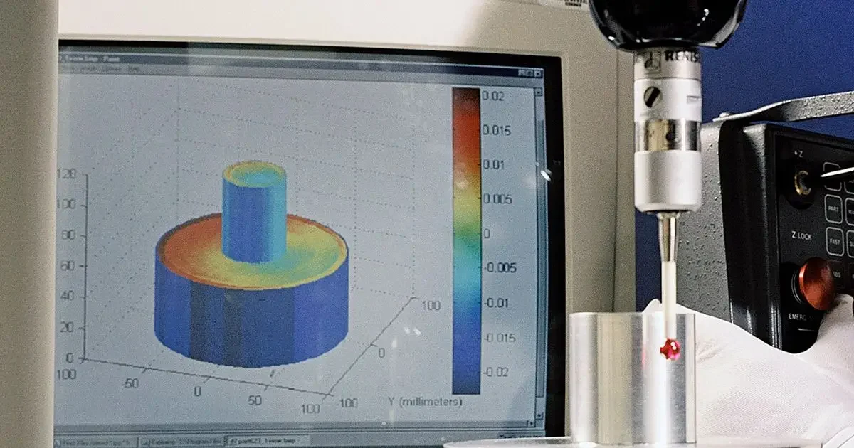
ZEISS states that coaxiality is now measured almost entirely digitally, using optical or tactile sensors, and that several values can be captured in one run. For a buyer this means a CMM report can show the alignment of every bore to the datum. Ask for these items in the first article report:
- Coaxiality or position value for each bore to the stated datum.
- The datum set up used, so the reading can be repeated.
- Bore diameter, roundness and cylindricity in the same report.
- Measurement temperature, since aluminum housings change size with temperature.
Total runout is cheaper to check on a rotating fixture but needs a good datum surface to turn on. Ask the shop which method its report uses.
Drawing mistakes that cause arguments
Most disputes over bore alignment come from the drawing and not from the machining. Five are easy to avoid:
- No datum. A coaxiality or position value with no datum reference has nothing to be coaxial to. Name the datum.
- Radius mistaken for diameter. The zone is a diameter. A designer who thinks of a 0.015 mm offset has to write 0.03 mm. State the diameter symbol next to the number.
- Mixed standards. An ISO coaxiality symbol on a drawing that cites ASME Y14.5 is read differently by different shops. Write the standard in the title block.
- Datum feature that is also the toleranced feature. If a bore is datum A, do not give the same bore an alignment value to A. Reference a second feature.
- General tolerances on the rest. If only the bearing bores carry an alignment value, the stator bore and flange pilot fall back to the general tolerance of the drawing. Decide whether that is acceptable and say so.
Checklist before you send the RFQ
- State the standard the drawing follows, ISO 1101 or ASME Y14.5.
- Define datum axes and name the feature that establishes each.
- Give a numeric alignment value as a diameter for each bore.
- Give the size class of each bore separately.
- Ask for form control on the bore: roundness or cylindricity.
- Ask for a first article report with the callouts listed above.
Where the drawing uses a flange, servo motor housings and mounting flanges lists the related pilot and face callouts. When the drawing is ready, send the RFQ and we quote the finished parts and place the work with a partner shop that machines motor parts, with a reply within 24 business hours.
See also: motor vibration grades under IEC 60034-14 for how bearing seat alignment reaches the vibration test.
Standards and references
- ZEISS Metrology, Coaxiality. Cylindrical zone, the half-diameter rule, causes of error and digital measurement.
- KEYENCE, GD&T symbol list. Plain wording for coaxiality, concentricity, true position and circular and total run-out.
- Geometric dimensioning and tolerancing, overview. Datums, position, run-out and the ASME and ISO 1101 structures. Concentricity removed from ASME Y14.5 in 2018.
- GD&T Basics, Coaxiality. ISO treatment of coaxiality and concentricity and the note that ASME differs.
- IT Grade, table of ISO 286 tolerance grades. IT6 and IT7 widths for the 50 to 80 mm range used in the example.
Figures on this page are typical ranges drawn from the standards above and from ordinary shop practice. They are not a specification for your part. The partner shop that prices your part confirms what it can hold on your geometry.
Frequently asked questions
What is the difference between coaxiality and concentricity?
Coaxiality controls the axes of two cylinders and concentricity controls center points, according to the KEYENCE symbol list. Under ISO one symbol serves both, and a mark for all cross sections turns it into concentricity. ASME Y14.5 removed concentricity in its 2018 revision, so check which standard your drawing follows.
Can I use total runout instead of coaxiality?
Often yes. Total runout is checked by rotating the part and covers the whole surface, so it limits form as well as alignment. Coaxiality or position is harder to measure but ties the axis to a datum axis directly. Agree the callout with the designer, since each reads a different thing.
Is a coaxiality value an offset or a diameter?
A diameter. The zone is a cylinder around the datum axis, so the axis may sit half the value away from it. ZEISS gives an example of a 0.3 mm zone, which is out of tolerance once the axis is more than 0.15 mm from the reference axis.
Does the bore size class control alignment?
No. A size class such as H7 limits the diameter of the bore. A bore can be within its size limits and still sit off the datum axis, which is why the drawing needs a separate numeric alignment callout.
Need a quote for this part?
Send the drawing. We quote the finished parts, place the work with a partner shop and reply within 24 business hours.
Get a quote for your motor part