Guides / Tolerances
Induction Hardened Shaft Journals: How to Specify Case Depth and Hardness
Written by the team that reads your RFQPublished How we write these
A bearing journal rides on rolling or sliding contact. It needs a hard surface to resist wear and a tough core to carry the shaft’s bending loads without cracking. Induction hardening delivers both on a medium carbon steel shaft, and it does so only where the coil heats, so the shaft can be hard under the bearings and soft everywhere else.
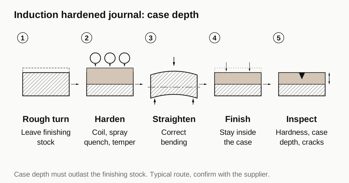
This guide explains how the process works, what case depth and hardness really mean and how to write a callout that a shop can quote and a lab can check.
How induction hardening works
The shaft sits inside or beside a copper coil carrying high frequency alternating current. The current induces heat in the shaft’s surface layer within seconds. When the layer reaches the austenite range, a water or polymer spray quenches it, and the heated layer turns into martensite, a hard structure. The core, which stayed cool, remains as it was.
Two settings control the result.
- Frequency. Higher frequency heats a thin layer near the surface and gives a shallow case. Lower frequency penetrates deeper.
- Heating time and power. Longer or stronger heating drives the heat deeper before the quench.
After quenching, the shaft is tempered, either in an oven at a low temperature or by self tempering from retained heat. Tempering reduces brittleness and lowers hardness slightly.
Induction hardening needs a steel with enough carbon to harden, generally around 0.35 to 0.55 percent. Common choices are carbon steels such as C45 and alloy steels such as 42CrMo4 or 4140.
Case depth, hardness and what they mean
Surface hardness is how hard the outer skin is, typically given in Rockwell C. For medium carbon steels that are induction hardened, values in the mid 50s to around 60 HRC are common, but the exact figure depends on the grade and the process. Alloy steels reach higher values than plain carbon steels for the same carbon level.
Case depth is how far the hardness extends. A number alone is meaningless without the criterion. Two definitions are in use.
- Effective case depth is the depth at which hardness falls to a stated level, often 550 HV or a similar value, depending on the standard used.
- Total case depth is the depth at which the structure and hardness match the core.
The drawing should say which one it means and which hardness level. ISO 18203 gives the method.
Depths for motor shafts usually sit in the range of a millimeter to a few millimeters. The right number depends on the load and on the grinding stock, so it is the designer’s call and not a general rule.
Why hardness and depth are linked to finishing
The shaft distorts during hardening. A journal that was turned to size before hardening grows, shrinks or goes slightly out of round. Finishing, by grinding or hard turning, removes the distortion, and the case has to be deep enough to survive that removal.
A simple calculation helps. Suppose the finishing allowance on diameter is 0.3 mm, so about 0.15 mm leaves each side. The case depth has to be the required working depth plus that 0.15 mm, and also plus a margin for the variation in case depth across a batch.
If the drawing states a final case depth after finishing, the shop works backwards to the as-hardened depth. If the drawing states the as-hardened depth, the shop sets the finishing allowance to keep enough case. Say which one applies. The comparison of grinding and hard turning explains the finishing step.
A table of what to state
| Item | What to write | Why |
|---|---|---|
| Material grade | For example 42CrMo4 or C45 with a standard | Hardness response depends on it |
| Hardened zones | Which journals, with axial limits | The coil covers only these |
| Surface hardness | Range in HRC, with test method | Wear resistance |
| Case depth | Value or range, with the hardness criterion and the standard | Load carrying |
| Depth state | Before or after finishing | Sets the stock |
| Tempering | Temperature or hardness after temper | Toughness |
| Soft zones | Keyways, splines and threads outside the hardened area | Avoids cracking and hard cutting |
Induction hardening against other routes
Induction hardening is one of several ways to get a hard surface on a shaft. The alternatives change what the drawing and the finishing look like.
Through hardening and tempering. The whole section is heated in a furnace and quenched, so the shaft is hard right through. It is simple, but the shaft is more brittle and distorts more, and cutting afterwards is difficult.
Carburizing. Low carbon steel is held in a carbon rich atmosphere so that carbon diffuses into the surface, then quenched. It gives a deep, hard case and a tough core and suits gears and heavily loaded shafts. It is a long furnace cycle and distorts the part more than induction.
Nitriding. Nitrogen diffuses into the surface at a low temperature, below the point where the steel changes structure. It gives a thin, very hard case with little distortion and needs no quench. Case depth is a fraction of a millimeter, so the surface cannot be ground much afterwards.
Induction hardening. Selective, fast and easy to repeat on a medium carbon steel. Distortion is lower than furnace routes, and the heat affects only the zones the coil covers.
| Route | Case depth, typical order | Distortion | Selective zones |
|---|---|---|---|
| Induction hardening | Fractions of a millimeter to a few millimeters | Low to moderate | Yes, by coil design |
| Carburizing | About 0.5 to 2 mm and more | Moderate to high | By masking |
| Nitriding | Fractions of a millimeter | Very low | By masking |
| Through hardening | Whole section | High | No |
The depth figures are orders of magnitude for orientation, and a heat treater quotes the real numbers for a given steel and size. Choosing the route is the designer’s decision. A buyer who reads a quote with a different route from the drawing should ask why, since swapping a route changes the finishing allowance and the properties.
Need a quote for this part? Get a quote for your motor part
Hardness testing and conversion
Hardness appears on drawings in several scales, and they do not convert exactly. Rockwell C (HRC) is the usual scale for hardened shafts. Vickers (HV) is the scale used for case depth profiles, because the small indent suits a gradient. Conversion tables between the two are approximate, and standards such as ISO 18265 give them with a warning that they apply to unalloyed and low alloy steels.
For a drawing, pick one scale for each purpose. State surface hardness in HRC. State the case depth criterion in HV, for example the depth at which hardness falls to 550 HV. A shop that has to convert between scales to meet a drawing will add a margin, and the margin is a cost.
Test locations matter too. A hardness test on the journal surface is simple. A test on the end of the hardened zone, where the transition lies, tells you more about the process but is harder to do. If the drawing needs a check at the transition, say where.
Distortion and how shops plan for it
Heat and a quench bend a slender shaft. The shop plans for this in three ways.
- Leave finishing stock on every hardened journal, sized from experience with the shaft’s length and diameter.
- Quench in a way that limits bending, with controlled spray patterns and rotation of the shaft in the coil.
- Straighten after hardening, in a press with a dial indicator, to bring runout within the limit the finishing step can fix.
Straightening hardened steel is a skilled step, since the shaft can crack if it is pushed too far. A shop that straightens shafts regularly has a method and a limit. If it cannot straighten, it must hold distortion low at the quench, which is slower and costs more.
Where the hardened zone ends
At the end of the hardened zone, hardness falls over a short transition. The transition is a stress concentrator and a place where the shaft can crack in service if it sits at a shoulder or a fillet.
Design rules that follow:
- Keep the transition away from sharp corners. A hardened zone that ends exactly at a fillet puts a hardness step on a stress raiser.
- Do not harden across a keyway or cross hole without a plan. The edges of a slot overheat and can crack in the quench.
- Leave spline and thread zones soft unless the design needs them hard and the shop can manage the risk. The guide on splines and keyways explains why those features are cut before hardening.
Inspection
A hardened journal is checked in several ways.
- Surface hardness with a Rockwell or a portable tester on each shaft or on a sample.
- Case depth by sectioning a sample from each lot and measuring a hardness profile.
- Cracks with magnetic particle inspection on critical shafts, since quench cracks are a known risk near sharp features.
- Distortion by measuring runout between journals before finishing, which tells the shop how much stock is needed.
Ask the shop which of these it runs on every shaft and which on a sample. A shop that takes a section per lot and keeps the photograph and the hardness profile has a record to show you.
Questions to ask a shop
- Do you harden in house or send out, and with what lead time?
- What case depth range do you hold on this diameter?
- How do you handle distortion on slender shafts?
- Do you check for cracks, and by which method?
- What do you do with a lot that falls below the minimum case depth?
Checklist before you send the RFQ
- State material grade and the standard.
- Show the hardened zones on the drawing with their limits.
- State surface hardness and case depth, with the criterion and the method.
- State whether the depth applies before or after finishing.
- Keep keyways and splines outside the hardened zone, or note how they are treated.
- State inspection on each shaft and on samples.
When the drawing is ready, send the RFQ and we quote the finished parts and place the work with a partner shop that machines motor shafts, with replies within 24 business hours.
See also: magnetic particle inspection of rotor shafts for where cracks start and what to specify.
Standards and references
- Induction hardening, overview of the process and typical results. How a coil heats the surface and a quench hardens it.
- Case-hardening, overview of surface hardening methods. Where induction hardening sits among carburizing, nitriding and other routes.
- ISO 18203, Steel, Determination of the thickness of surface-hardened layers. The method and definitions behind case depth numbers. Check the current edition.
- ISO 6508-1, Metallic materials, Rockwell hardness test. How HRC values on the drawing are measured.
Figures on this page are typical ranges drawn from the standards above and from ordinary shop practice. They are not a specification for your part. The partner shop that prices your part confirms what it can hold on your geometry.
Frequently asked questions
Which case depth should I put on the drawing?
The depth comes from the load and the finishing stock: it has to be deep enough to carry contact stress under the bearing and still leave hardened metal after the finishing pass removes its allowance. The motor designer sets the number. A drawing that names a range and the hardness at the depth that counts is clearer than a single value.
How is case depth measured?
By sectioning a sample, polishing the section and measuring hardness at steps from the surface. The depth is where hardness falls to a stated level, commonly given in Vickers. ISO 18203 describes the method. The drawing should state the hardness level used.
Can a shop machine after induction hardening?
Yes, with grinding or hard turning, as long as the removal stays inside the case. Cutting a keyway or a spline after hardening is much harder and often avoided by cutting them first and keeping them outside the hardened zone.
Need a quote for this part?
Send the drawing. We quote the finished parts, place the work with a partner shop and reply within 24 business hours.
Get a quote for your motor part