Guides / For Shops
Measuring Bearing Bores In-Process: Air Gauge or CMM
Written by the team that reads your RFQPublished How we write these

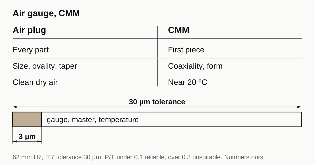
Use an air gauge on the machine for every part, and use a CMM or roundness instrument on a schedule for the features an air plug cannot see and to prove the air gauge is right. The two do different jobs, and most disputes over bearing bore readings come from asking one of them to do the other’s job. This guide covers what each measures, how much measurement error a bore tolerance can absorb and a routine that holds up when the buyer’s report disagrees with yours.
What an air plug measures
An air gauge blows compressed air through precision jets toward the part and reads the back pressure. A larger gap gives lower back pressure. An air plug for a bore usually carries two jets 180 degrees apart on a steel cylinder, so the reading is the diameter across those jets.
A trade article in Quality Digest lists what makes it attractive at the machine:
- Practical resolution of 50 microinches (about 1.3 µm), and about 5 microinches (about 0.13 µm) with care.
- No contact force, so thin walls do not distort.
- The jet clears dust, chips and cutting fluid from the surface as it measures.
- Several features can be read at once on a fixture.
The same article lists the limits, and they matter for a motor housing. Range is short, roughly 0.003 in (0.076 mm) at most. It is poorly suited to rough surfaces. It needs clean, dry compressed air. Treat these as typical figures from one trade source and check them against your own gauge maker’s data.
Turning the plug 180 degrees in the bore shows whether the bore is out of round, and moving it along the bore shows taper. Those two checks are the reason an air plug earns its place on a bearing seat.
What a CMM measures
A coordinate measuring machine touches or scans the part and builds features from the measured points. Wikipedia gives typical probe repeatability within about one micron, with scanning probes often more accurate and usually faster than single-point touch probing. Measured points can construct a cylinder and assess roundness, so a CMM can report diameter, roundness, cylindricity and, importantly for a motor housing, the relationship between features.
That last point is what an air plug cannot do. Two bearing bores at opposite ends of a housing must share an axis, and the bearing bore coaxiality guide shows how the drawing states it. An air plug reads each bore’s size but not whether the two axes line up. A CMM can.
A CMM result is not a single truth, though. The same measured points give a different roundness error depending on the reference circle: least squares, minimum zone, minimum circumscribed or maximum inscribed. On a bore that is slightly lobed the diameters differ between those fits. If your CMM report says 62.014 and your air gauge says 62.011, check the fitting method before anything else. Write the method on the report and use it every time.
Comparison
| Air plug | Dial or three-point bore gauge | CMM | |
|---|---|---|---|
| Best use | Every part at the machine | Quick check, setup, spot checks | First piece, periodic checks, coaxiality and position |
| Measures | Diameter, ovality, taper of one bore | Diameter at the points touched | Many points, so form and relation between features |
| Operator effect | Low | Higher: tilt and feel | Low once programmed |
| Cleanliness | Needs clean dry air, jet clears the surface | Part must be clean | Part must be clean and near 20 °C |
| Limit to watch | Short range, rough surfaces, master quality | Setting method sets the accuracy | Fit method, probe qualification, temperature |
How much error a bore tolerance can absorb
Gauge R&R guidance expresses measurement error as a share of the tolerance. A P/T ratio under 0.1 (10 percent) is described as reliable, and over 0.3 (30 percent) as inappropriate for the process.
Take a 62 mm bearing bore at H7. The ISO 286 grade IT7 for the 50 to 80 mm size band is 30 µm, the same figure printed on the bearing fit tolerance reference. Ten percent of 30 µm is 3 µm. Everything has to fit inside that: the repeatability of the gauge, the error of the setting master, operator effect and temperature.
Setting the instrument is the first place the budget goes. Wikipedia describes setting a dial bore gauge with an outside micrometer as the quickest and least expensive method but less accurate, at about 0.002 in (0.05 mm). A master ring or setting equipment built on gauge blocks can reach within about 0.0001 in (2.5 µm). On a 30 µm tolerance the micrometer method uses more than the whole tolerance by itself, and even the ring master takes most of the 3 µm budget. For an H7 bearing seat, set air plugs and bore gauges on a calibrated master ring and keep the certificate.
Temperature takes the rest
Length measurements are referenced to 20 °C under ISO 1. Aluminium has a linear expansion coefficient of 23.1 × 10⁻⁶ per kelvin and carbon steel 10.8 × 10⁻⁶ per kelvin.
A worked case for the same 62 mm bore:
- Aluminium housing, 1 K above 20 °C: 62 mm × 23.1 × 10⁻⁶ = 0.00143 mm, about 1.4 µm.
- Steel master ring at 20 °C and a housing 3 K warm from the cut: the bore reads about 4.3 µm large.
Three kelvin of warm part is more than the whole 3 µm budget. Two habits fix most of it. Let housing and master reach the same temperature before measuring, and keep the setting master next to the machine so it follows the shop temperature. If parts must be measured warm, apply a documented correction and say so on the report.
Need a quote for this part? Get a quote for your motor part
A routine that uses both
- Set the air plug on a ring master with a current calibration certificate. Log who set it and when.
- Correlate once. Measure a first piece on the CMM and on the air plug, record the offset between them and write down the CMM fitting method. If they disagree by more than your budget allows, find out why before production.
- Measure every part with the air plug at the machine. Read diameter at two or more depths and turn the plug to catch ovality.
- Chart the readings. The air gauge feeds the control chart that drives tool offsets. The SPC guide for bearing bores shows what to report from it.
- Put a part on the CMM on a schedule and on every setup change, tool change or master recalibration. Check coaxiality, position and form there.
- Recheck the master on its calibration interval and after any drop or contamination.
Deciding conformity near the limit
When a result sits close to a tolerance limit, the measurement uncertainty decides whether the part is in or out. ISO 14253-1 is the standard that sets decision rules for exactly this case, including what to do when a result falls inside the uncertainty range around a limit. Many drawings do not say which rule applies, so agree it with the buyer before the first order. Without an agreed rule, two honest reports of the same bore can disagree and neither is wrong. Include the instrument, the master and the fit method on the first article report so the buyer can see what was done. The PPAP guide for motor parts lists where those studies sit in the package.
When the two disagree
Check in this order:
- Temperature of the part and the master.
- The master: certificate, damage, cleanliness.
- Surface finish. An air gauge reads differently on a rough bore than on a ground one.
- Roundness. If the bore is lobed, a two-jet reading depends on where the plug sits.
- The CMM fitting method and probe qualification.
If you are quoting bearing bore work and want to show the buyer what you measure with, the guide on winning motor part work explains why naming the instrument and method in the first reply helps.
A buyer’s view of the same measurement question, which callouts a housing needs and what the report must show, is in the motor housing tolerances guide.
If you machine motor housings and want work requests that fit your machines, apply as a partner shop. There is no fee to join, no charge per request and no promise of orders. You quote us, and we place the purchase order if price and lead time work.
Sources
- Quality Digest, Gage guide, air gaging
- Coordinate-measuring machine, overview
- Bore gauge, overview
- Cylindricity and roundness, overview
- Gauge R&R, overview
- ISO 1, standard reference temperature
- Thermal expansion, overview
- ISO 14253-1, catalogue entry
Standards and references
- Quality Digest, Gage guide, air gaging (1996). How an air gage reads back pressure, its resolution, its short range, the cleaning effect of the jet and the plug test for out-of-round. Trade article, directional for the figures.
- Coordinate-measuring machine, overview. Touch-trigger and scanning probes, typical probe repeatability, how measured points build cylinders for roundness, and ISO 10360 probing terms.
- Bore gauge, overview. Dial bore gauge as a comparative instrument, and the setting accuracy of a micrometer against a master ring.
- Cylindricity and roundness, overview. Roundness error depends on the reference circle used: least squares, minimum zone, minimum circumscribed or maximum inscribed.
- Gauge R&R, overview. The P/T ratio: under 0.1 reliable, over 0.3 inappropriate.
- ISO 1, standard reference temperature for geometrical product specifications. 20 °C as the reference temperature for industrial length measurement.
- Thermal expansion, overview. Linear coefficients at 20 °C: aluminium 23.1, carbon steel 10.8 (×10⁻⁶ per K).
- ISO 14253-1, decision rules for proving conformity or nonconformity with specifications (catalogue entry). Scope: rules for judging conformity while accounting for measurement uncertainty, including results that fall inside the uncertainty range around a limit. The 2013 edition shown is withdrawn and replaced by the 2017 edition.
Figures on this page are typical ranges drawn from the standards above and from ordinary shop practice. They are not a specification for your part. The partner shop that prices your part confirms what it can hold on your geometry.
Frequently asked questions
Can an air gauge replace a CMM for checking a bearing bore?
For size, ovality and taper of one bore on every part, an air plug is often the better tool at the machine. It does not give coaxiality between two bores or position to a datum. Keep a CMM or roundness instrument for those features and for checking the air gauge itself.
How accurate does the bore gauge need to be for an H7 bore?
Gauge R&R guidance puts a reliable system under 10 percent of the tolerance and an unsuitable one over 30 percent. On a 62 mm H7 bore, IT7 is 30 µm, so the whole measurement budget is about 3 µm, including master, gauge and temperature effects.
Why does the CMM read a different bore size than the air gauge?
The two instruments sample the bore differently, and a CMM result depends on the fitting method chosen. Least squares, minimum circumscribed and maximum inscribed circles give different diameters on a bore that is not perfectly round. Record the method on the report and use the same one every time.
Does temperature really matter when measuring a motor housing?
Yes. The reference temperature for length measurement is 20 °C. Aluminium expands at about 23.1 µm per metre per kelvin, so a 62 mm bore grows about 1.4 µm per kelvin. A housing a few kelvin warm off the machine consumes the whole error budget of an H7 bore.
Need a quote for this part?
Send the drawing. We quote the finished parts, place the work with a partner shop and reply within 24 business hours.
Get a quote for your motor part