Guides / Tolerances
Axial Flux Motor Housings and Rotor Discs: Flatness, Parallelism and Air Gap Control
Written by the team that reads your RFQPublished How we write these
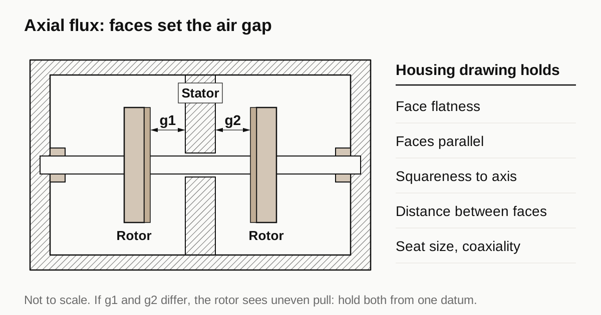
In an axial flux motor the air gap sits between facing surfaces, so the housing drawing needs more than bore tolerances. Each mating face needs a flatness limit. The two faces that face the rotor need a parallelism limit. Each face needs squareness to the bearing axis and the distance between faces needs a size tolerance. All of them refer to one datum scheme, because the gap is the sum of these contributions.
Why the gap is set differently than in a radial motor
In a radial motor the air gap is a thin ring between a rotor diameter and a stator bore. Two fits control it. In an axial flux motor the gap runs parallel to the rotation axis and the flux crosses it axially, so the gap is a distance between two flat faces. Wikipedia describes these motors as shorter and wider than a radial motor of the same output, with a rotor that is typically much wider and so has more inertia and more centrifugal load.
Layouts differ. Single stator with dual rotors can omit the yoke, which saves weight. Dual stator with a single rotor is more common at high power but needs a yoke, that is, a housing that carries flux. The housing therefore does a different job in each layout, and the drawing must show which faces set the gap.
A patent on axial flux machine manufacture gives a feel for the scale. It states the air gap may be less than 3, 2 or 1 millimetres and that it should be as small as possible, because the gap is a high reluctance path. The same patent describes controlling end wall spacing to better than 100 micrometres and gives, as an example, a stator wall flat within 0.2 mm that the jig then absorbs. These are values from one patent for one construction method, not tolerances to copy. They show that gap and spacing are discussed in tenths and hundredths of a millimetre.
The callouts a housing drawing needs
| Callout | What it controls | Why it matters for the gap |
|---|---|---|
| Flatness of each mating face | How far the high and low points of the face deviate | A bowed face makes the gap vary around the circle |
| Parallelism of face to face | How closely one face matches the orientation of the other | Tilt makes one side of the gap wider than the other |
| Squareness to the bearing axis | How closely the face sits at a right angle to the datum axis | A tilted face tilts the stator or rotor on the axis |
| Distance between faces | Size tolerance on the stack height | Sets the mean gap |
| Bearing seat size and coaxiality | Where the rotor axis sits | Keeps the rotor from touching one side |
The wording for flatness, parallelism and perpendicularity follows the KEYENCE symbol list. It describes flatness as limiting the most protruded and the most concave part, parallelism as how accurately two planes are parallel to a datum and perpendicularity as how accurately a target is perpendicular to a datum.
A face that must be square to the axis can also take a total run-out callout. KEYENCE describes total run-out as the run-out of the entire surface when the target is rotated. It combines squareness and flatness in one reading, measured while the part turns. Which callout fits depends on how the part is inspected and what the designer needs, so ask before the RFQ.
A worked gap budget
The numbers below are illustrative. They show how contributions add and are not a recommended tolerance set. Assume a nominal gap of 1.0 mm per side and four contributors to variation, each given 0.05 mm on the drawing:
| Contributor | Allowed variation (mm) |
|---|---|
| Housing face flatness | 0.05 |
| Housing face parallelism | 0.05 |
| Rotor disc face flatness | 0.05 |
| Rotor disc squareness to its hub | 0.05 |
| Worst case sum | 0.20 |
| Root sum of squares | 0.10 |
If every contributor sits at its limit in the same direction, the gap moves by 0.20 mm, which is 20 percent of the nominal. If the variations are independent and random, the root sum of squares gives 0.10 mm. A designer picks the method that suits the risk. Either way, halving the nominal gap doubles the share that the same errors take. That is why tighter gap designs ask for flatter faces.
Rotor discs
A rotor disc is a wide, thin part. Magnets sit on or in it and their pull toward the stator loads the disc in bending. The disc has to stay flat under that load and under clamping on the machine. The guide on thin-wall machining without distortion covers the same effects on housings: rough, relieve stress, then finish with light cuts and a soft hold.
For the disc, ask the shop three things. How is the disc held for the finishing cut? Are both faces finished in the same setup or is the part turned over? How is flatness checked on the free part? The magnet seating face and the face that sees the stator may be separate features with separate limits, so mark both.
Need a quote for this part? Get a quote for your motor part
Shims and adjustment
The patent describes placing shims of different thickness between the mating surfaces of stator halves to tilt them and cancel a tolerance related inclination. Not every design does this. If the designer plans a shim stage, the drawing can carry looser parallelism on the housing and a measured shim at assembly. If not, the housing has to hold parallelism by itself. Ask which one applies, since the machining cost differs.
Measuring flat faces and gaps
ZEISS notes that coaxiality is now measured almost entirely digitally with optical or tactile sensors. The same equipment maps flatness and parallelism on faces. Ask for a first article report that lists flatness and parallelism for each gap-setting face and the datum scheme used. Where a rotor and stator are assembled for a trial, the gap measured around the circumference tells you more than any single part report.
Bearings and the tolerance chain
The bearings decide where the rotor stack sits between the stator faces. If a bearing is mounted into the housing the way it is in a radial motor, the chain from stator face to rotor face runs through housing dimensions as well as the shaft and the rotor discs, and every link adds variation. That is engineering reasoning. The patent above says that where one rotor is mounted on the other the layout imposes a requirement for particularly high tolerances, and that a labyrinth seal between rotor and stator imposes very tight tolerance constraints, without giving figures.
For the housing, the practical point is which dimension carries the gap. Ask the designer which datum faces and which shoulder set the axial position of each bearing, and give those features size tolerances tighter than the rest. Axial position of a bearing shoulder and squareness of the shoulder to the bore deserve the same care as the bore size. The reference on bearing fits, concentricity and runout covers shoulders and seats for radial cases.
The radial housing callouts (bores, shoulders and finishes) are in our motor housing tolerances guide.
Checklist before you send the RFQ
- Layout of the motor: single or dual rotor, and which housing faces set the gap.
- Flatness, parallelism and squareness values on the gap-setting faces, from the designer.
- Distance between the faces with a size tolerance.
- Bearing seat sizes and coaxiality, tied to the same datum. See bearing fits, concentricity and runout.
- Material of housing and rotor disc, and any coating that changes the faces.
- Whether the design assumes a shim stage at assembly.
For mounting faces on round motors the guide on servo motor housings and flanges lists related callouts. When the drawing is ready, send the RFQ and we quote the finished parts and place the work with a partner shop, with a reply within 24 business hours.
Standards and references
- Axial flux motor, overview. Geometry, single and dual rotor layouts and the case for a housing yoke.
- US10608512B2, Axial flux machine manufacture. Gap size, end wall spacing control, flatness example and the use of a jig, from one patent.
- KEYENCE, GD&T symbol list. Plain wording for flatness, parallelism, perpendicularity and run-out.
- ZEISS Metrology, Coaxiality. Causes of lost coaxiality and digital measurement.
Figures on this page are typical ranges drawn from the standards above and from ordinary shop practice. They are not a specification for your part. The partner shop that prices your part confirms what it can hold on your geometry.
Frequently asked questions
How flat does an axial flux rotor disc need to be?
There is no universal figure. The designer sets it from the air gap and the other contributors to the gap, so a smaller gap needs a flatter disc. Ask the motor designer for the gap target and the share of it given to the disc, then put that value on the drawing.
Why is the air gap harder to hold than in a radial motor?
In a radial motor the gap is set by two diameters that fit together. In an axial flux motor it is set by the distance between facing surfaces, so flatness, parallelism and squareness to the bearing axis all add up in the gap. The housing carries several of those faces.
Do axial flux motors need a cast housing?
Not necessarily. The overview notes that flat components need no specialised casting or tooling. A patent on housing manufacture adds that molded housings find it hard to combine a strong structure with a very small gap. Machined plate and ring parts are common for that reason.
Which axial flux layout needs a yoke housing?
Dual stator with a single rotor designs need a yoke, which is part of the housing and adds iron losses. Single stator with dual rotor designs can omit the yoke. The layout changes which faces on the housing set the gap, so check it before the RFQ.
Need a quote for this part?
Send the drawing. We quote the finished parts, place the work with a partner shop and reply within 24 business hours.
Get a quote for your motor part